


v
MODEL 3081 pH/ORP TABLE OF CONTENTS
TABLE OF CONTENTS - CONT’D
LIST OF FIGURES - CONT’D
Number Title Page
3-23 Procedure for Removing BNC Connector and Preparing Coaxial Cable for............
Connection to the Model 3081 pH/ORP Transmitter................................................ 26
3-24 Preparation of Raw Connecting Cable (PN 9200273).............................................. 27
4-1 Intrinsically Safe BASEEFA Model 3081 pH/ORP Label .......................................... 31
4-2 FMRC Installation for Model 3081 pH/ORP Transmitter........................................... 32
4-3 CSA Installation for Model 3081 pH/ORP Transmitter.............................................. 34
4-4 Explosion-Proof Installation for Model 3081 pH/ORP Transmitter............................ 36
5-1 Process Display Screen ........................................................................................... 37
5-2 Program Display Screen .......................................................................................... 37
5-3 Infrared Remote Controller....................................................................................... 38
5-4 Menu Tree for pH ..................................................................................................... 39
5-5 Menu Tree for ORP ................................................................................................. 40
6-1 Connecting the HART Communicator ...................................................................... 42
6-2 Menu Tree for pH (HART) ........................................................................................ 44
6-3 Menu Tree for ORP (HART) ..................................................................................... 46
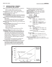
8-1 Suggested Glass Impedance Warning and Failure Limits ....................................... 60
8-2 Suggested Warning and Failure Limits for Low Impedance Reference Electrodes . 61
8-3 Suggested Warning and Failure Limits for High Impedance Glass Reference .......
Electrodes ................................................................................................................ 61
10-1 Suggested Warning and Failure Limits for Low Impedance Reference Electrodes . 79
10-2 Suggested Glass Impedance Warning and Failure Limits for a Glass Reference....
Electrode .................................................................................................................. 79
11-1 Exploded View of Model 3081 pH/ORP Transmitter................................................. 85
11-2 Checking the Potential of the Reference Electrode.................................................. 87
12-1 Warning Annunciation............................................................................................... 89
12-2 Fault Annunciation.................................................................................................... 89
12-3 Three-Wire RTD .................................................................................................... 96
12-4 Temperature Simulation into the Model 3081 pH/ORP Transmitter ......................... 97
12-5 Troubleshooting Flow Chart/Preamplifier in Sensor-Mounted Junction Box or........
Remote Junction Box ............................................................................................... 108
12-6 Troubleshooting Flow Chart/Preamplifier in Transmitter or Built into Sensor........... 109
12-7 pH Simulation When the Preamplifier is Located in the Transmitter ........................ 111
12-8 pH Simulation When the Preamplifier is Located in a Remote Junction Box or.......
in a Sensor-Mounted Junction Box .......................................................................... 111
12-9 Simulate pH Through Model 381+ Sensor Preamplifier........................................... 112
13-1 pH Measurement Cell............................................................................................... 114
13-2 Measuring Electrode (pH) ........................................................................................ 115
13-3 Cross-Section Through the pH Glass....................................................................... 115
13-4 Reference Electrode................................................................................................. 116
13-5 The Origin of Liquid Junction Potential..................................................................... 116
13-6 Glass Electrode Slope.............................................................................................. 117
13-7 Two-Point Buffer Calibration..................................................................................... 118
13-8 Liquid Junction Potential Mismatch .......................................................................... 119
14-1 ORP Measurement Cell ........................................................................................... 120
14-2 Measuring Electrode (ORP) ..................................................................................... 121
14-3 Reference Electrode................................................................................................. 121
14-4 The Origin of Liquid Junction Potential..................................................................... 122
14-5 Electrode Potential ................................................................................................... 122
14-6 ORP Measurement Interpretation............................................................................. 123
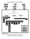
15-1 HART Communications ........................................................................................... 126
15-2 AMS Main Menu Tools ............................................................................................. 127