


17
MODEL 3081 pH/ORP SECTION 3.0
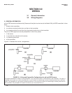
WIRING
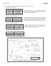
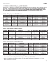
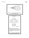
Table 3-7 Wiring Diagrams for Model 385+ Sensors
Sensor Junction Box Preamplifier RTD Wire Functions Wiring Diagram
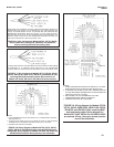
385+ -02 sensor-mounted in sensor-mounted junction box Pt 100 Figure 3-15 Figure 3-16
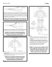
385+ -03 none in sensor Pt 100 Figure 3-13 Figure 3-14
385+ -03 remote in sensor Pt 100 Figure 3-13 Figure 3-14
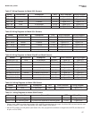
385+ -04 none in transmitter Pt 100 Figure 3-10 Figure 3-11
385+ -04 remote in remote junction box Pt 100 Figure 3-10 Figure 3-12
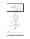
Table 3-8 Wiring Diagrams for Model 381+ Sensors
Sensor Junction Box Preamplifier RTD Wire Functions Wiring Diagram
381+ -40-55 none in sensor Pt 100 Figure 3-13 Figure 3-14
381+ -43-55 none in sensor Pt 100 Figure 3-13 Figure 3-14
381+ -40-55 remote in sensor Pt 100 Figure 3-13 Figure 3-14
381+ -43-55 remote in sensor Pt 100 Figure 3-13 Figure 3-14
381+ -41-52 none in transmitter Pt 100 Figure 3-10 Figure 3-11
381+ -41-52 remote in remote junction box Pt 100 Figure 3-10 Figure 3-12
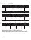
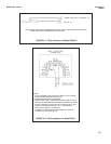
Table 3-9 Wiring Diagrams for Model 381pHE and 381pH Sensors
Sensor Junction Box Preamplifier RTD Wire Functions Wiring Diagram
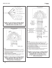
381pH-30-41-52* none in transmitter 3K Balco** Figure 3-2 Figure 3-4
381pH-30-41-52* remote in remote junction box 3K Balco** Figure 3-2 Figure 3-5
381pH-30-42-52 none in transmitter 3K Balco** Figure 3-3 Figure 3-4
381pH-30-42-52 remote in remote junction box 3K Balco** Figure 3-3 Figure 3-5
381pHE-31-41-52* none in transmitter Pt 100 Figure 3-2 Figure 3-4
381pHE-31-41-52* remote in remote junction box Pt 100 Figure 3-2 Figure 3-5
381pHE-31-42-52 none in transmitter Pt 100 Figure 3-3 Figure 3-4
381pHE-31-42-52 remote in remote junction box Pt 100 Figure 3-3 Figure 3-5
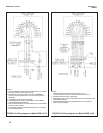
Table 3-10 Wiring Diagrams for Model 328A Sensor
Sensor Junction Box Preamplifier RTD Wire Functions Wiring Diagram
328A none in transmitter none Figure 3-17 Figure 3-18
Table 3-11 Wiring Diagrams for Model 320HP Sensor
Sensor Junction Box Preamplifier RTD Wiring Diagram
320HP-10-55 on mounting plate in transmitter Pt 100 Figure 3-19
320HP-10-58 on mounting plate in junction box attached to mounting plate Pt 100 Figure 3-20
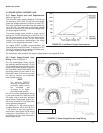
* Sensors have a BNC connector that the Model 3081 pH/ORP transmitter does not accept. Cut off the BNC and terminate the coaxi-
al cable as shown in Figure 3-23. Alternatively, use a BNC adapter (PN 9120531).
** Set the RTD jumper to the 3K position (see Section 2.2). Also, program the transmitter to recognize the 3K RTD (see Section 8.5
for pH or 10.5 for ORP).