


iv
MODEL 3081 pH/ORP TABLE OF CONTENTS
TABLE OF CONTENTS CONT’D
LIST OF FIGURES
Number Title Page
2-1 Model 3081 pH/ORP Transmitter - Exploded Drawing of Circuit Board Stack ......... 8
2-2 Model 3081 pH/ORP Transmitter - Analog Board .................................................... 9
2-3 Model 3081 pH/ORP Transmitter - CPU Board........................................................ 10
2-4 Mounting the Model 3081 pH/ORP Transmitter on a Flat Surface........................... 11
2-5 Using the Pipe Mounting Kit to Attach the Model 3081 pH/ORP Transmitter to a Pipe . 12
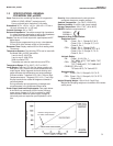
2-6 Load/Power Supply Requirements .......................................................................... 13
2-7 Power Supply/Current Loop Wiring .......................................................................... 13
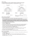
3-1 Wiring and Preamplifier Configurations for pH and ORP Sensors........................... 14
3-2 Wire Functions for Models 399-02, 399-09, 381pH-30-41, and 381pHE-31-41.......
before removing BNC and terminating cable ........................................................... 18
3-3 Wire Functions for Models 399-02, 399-09, 381pH-30-41, and 381pHE-31-41.......
after removing BNC and terminating cable. Wire Functions for Models ..................
399-09-10-62, 381pH-30-42, and 381pHE-31-42 as received................................. 18
3-4 Wiring Diagram for Models 399-02, 399-09, 381pH-30-41, and 381pHE-31-41 after
removing BNC and terminating cable. Wiring Diagram for Models ..399-09-10-62,
381pH-30-42, and 381pHE-31-42 as received. Wiring directly to the transmitter. ... 18
3-5 Wiring Diagram for Models 399-02, 399-09, 381pH-30-41 after removing BNC and
terminating cable. Wiring Diagram for Model 399-09-10-62, 381pH-30-42, and .....
381pHE-31-42 as received. Wiring through a remote junction box to the transmitter . 18
3-6 Wire Functions for Models 397-50, 397-54, 396-50, 396-54, 396R-50-60, 396R-54-60,
389-02-50, and 389-02-54 before removing BNC and terminating cable................. 19
3-7 Wire Functions for Models 397-50, 397-54, 396-50, 396-54, 396R-50-60, 396R-54-60,
389-02-50, and 389-02-54 after removing BNC and terminating cable. Wire .........
Functions for Models 397-54-62, 396-54-62, and 389-02-54-62 as received .......... 19
3-8 Wiring Diagram for Models 397-50, 397-54, 396-50, 396-54, 389-02-50, and.........
389-02-54 after removing BNC and terminating cable. Wiring Diagram for ............
Models 397-54-62, 396-54-62, and 389-02-54-62 as received. Wiring Directly.......
to the Transmitter ................................................................................................... 19
3-9 Wiring Diagram for Models 397-50, 397-54, 396-50, 396-54, 396R-50-60, 396R-54-60,
389-02-50, and 389-02-54 after removing BNC and terminating cable. Wiring ......
Diagram for Models 397-54-62, 396-54-62, and 389-02-54-62 as received. ..........
Wiring Through a Remote Junction Box to the Transmitter ..................................... 19
3-10 Wire Functions for Models 396R-50, 396R-54, 396R-54-61, 396P-02-50, ..............
396P-02-54, 396P-02-55, 385+-04, and 381+-41-52............................................... 20
3-11 Wiring Diagram for Models 396R-50, 396R-54, 396R-54-61, 396P-02-50, 396P-02-54,
396P-02-55, 385+-04, and 381+-41-52. Wiring Directly to the Transmitter ............ 20
3-12 Wiring Diagram for Models 396R-50, 396R-54, 396R-54-61, 396P-02-50, .............
396P-02-54, 396P-02-55, 385+-04, and 381+-41-52. Wiring Through a Sensor-....
Mounted Junction Box to the Transmitter ................................................................ 20
3-13 Wire Functions for Models 396P-01-55, 385+-03, 381+-40-55, and 381+-43-55 .... 21
3-14 Wiring Diagram for Models 396P-01-55, 385+-03, 381+-40-55, and 381+-43-55.... 21
3-15 Wire Functions for Model 385+-02 ........................................................................... 22
3-16 Wiring Diagram for Model 385+-02 .......................................................................... 22
3-17 Wire Functions for Model 328A-07........................................................................... 23
3-18 Wiring Diagram for Model 328A ............................................................................... 23
3-19 Wiring Diagram for Model 320HP-10-55 .................................................................. 24
3-20 Wiring Diagram for Model 320HP-10-58 .................................................................. 24
3-21 Wire Functions for Model 399-33 ............................................................................. 25
3-22 Wiring Diagram for Model 399-33 ............................................................................ 25