


105
MODEL 3081 pH/ORP SECTION 12.0
TROUBLESHOOTING
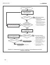
12.5.8 Buffer Calibration Is Acceptable; Process pH is Grossly Different from Expected Value.
The symptoms suggest a ground loop (measurement system connected to earth ground at more than one point), a float-
ing system (no earth ground), or noise being induced into the transmitter by sensor cabling. The problem arises from the
process or installation. It is not a fault of the transmitter. The problem should disappear once the sensor is taken out of the
system.
A. To confirm a ground loop...
1. Verify that the system works properly in buffers. Be sure there is no direct electrical connection between the
buffer containers and the process liquid or piping.
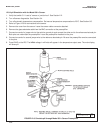
2. Strip back the ends of a heavy gauge wire. Connect one end of the wire to the process piping or place it in the
processliquid. Place the other end of the wire in the container of buffer with the sensor. The wire makes an
electrical connection between the process and sensor.
3. If similar symptoms develop after making the connection, a ground loop exists. If no symptoms develop, a ground
loop may or may not exist.
B. Check the grounding of the process.
1. The measurement system needs one path to ground: through the process liquid and piping. Plastic piping, fiber
glass tanks, and ungrounded or poorly grounded vessels do not provide a path. A floating system can pick up
stray voltages from other electrical equipment.
2. Ground the piping or tank to a local earth ground. Metal tees, grounding rings, or grounding rods may be
required.
3. If problems persist, connect a wire from the the ground connection at the dc power supply to the transmitter case.
Connect a second wire from the transmitter case to the process. These connections force the grounds to the
same potential.
4. If the problem persists, simple grounding is not the problem. Noise is probably being carried into the instrument
through the sensor wiring. Go to step C.
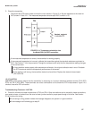
C. Simplify the sensor wiring.
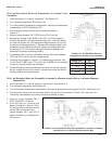
1. Disconnect all sensor wires at the transmitter except: TB-4 (RTD SNS), TB-5 (RTD IN), TB-7 (REF IN), and TB-10
(pH/ORP IN). If a remote preamplifier is being used, disconnect the wires at the input side of the junction box.
2. Tape back the ends of the disconnected wires, including all shield and drain wires, to keep them from making
accidental connections with other wires, terminals, or the transmitter case.
3. Connect a jumper wire between TB-3 (RTD RTN) and TB-4 (RTD-SNS). Connect a second jumper wire between
TB-7 (REF IN) and TB-8 (SOL GND).
4. Place the sensor back in the process liquid. If diagnostic messages such as GLASSFAIL or REF WArn appear,
turn off the sensor diagnostics. See Section 8.4.
If the symptoms disappear, interference was coming into the transmitter along one of the sensor wires. The
measurement system can be operated permanently with the simplified wiring.
If symptoms still persist, go to step D.
D. Check for extra ground connections or induced noise.
1. The electrode system is connected to earth ground through the process. If other ground connections exist, there
are multiple paths and ground loops are present. Noise enters the measurement either by a direct connection,
usually between the cable and grounded metal, or by an indirect connection, usually EMI/RFI picked up by the
cable.
2. If the sensor cable is run inside conduit, there may be a short between the cable and the conduit. Re-run the
cable outside the conduit. If symptoms disappear, then a short exists between the cable and the conduit. Likely a
shield is exposed and is touching the conduit. Repair the cable and reinstall it in the conduit.
3. To avoid induced noise in the sensor cable, run it as far away as possible from power cables, relays, and electric
motors. Keep sensor wiring out of crowded panels and cable trays.