


9
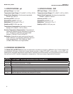
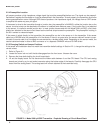
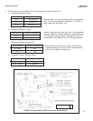
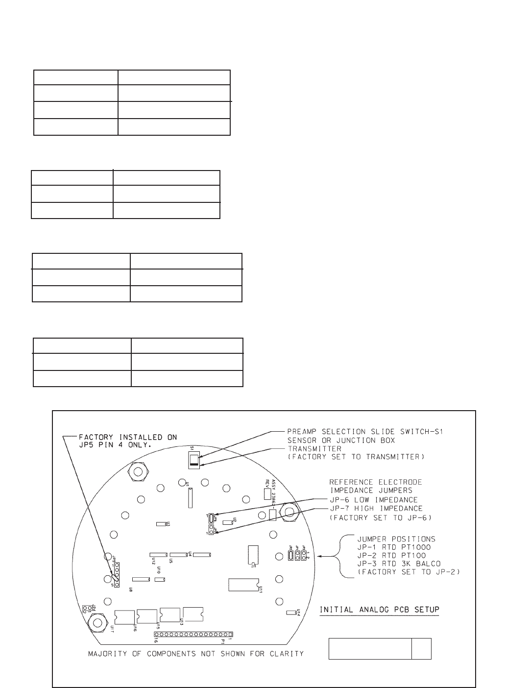
5. Set the jumpers and the slide switch on the analog board. Refer to Figure 2-2.
a. Temperature element jumper.
Jumper position Temperature element
JP-1 Pt 1000 RTD
JP-2 Pt 100 RTD
JP-3 3K Balco RTD
b. Reference impedance jumper.
Jumper position Reference impedance
JP-6 low
JP-7 high
c. Reference impedance jumper JP-5.
Jumper position Reference impedance
Pin 4 only low
Pin 3 and Pin 4 high
d. Preamplifier location selection switch.
Move slider toward Preamplifier location
edge of board sensor or junction box
center of board transmitter
MODEL 3081 pH/ORP SECTION 2.0
INSTALLATION
FIGURE 2-2. Model 3081 pH/ORP Transmitter Analog Board
DWG. NO. REV.
40308110 H
The transmitter must also be programmed to recognize the
RTD. If pH is being measured, see Section 8.5. If ORP is
being measured, see Section 10.5.
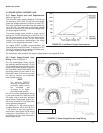
If sensor diagnostics are to be used with a high impedance
reference electrode, the high impedance must be identified
in the diagnostics setup program. See Section 8.4 for pH
measurements. See Section 10.4 for ORP measurements.
Leave jumper connected on Pin 4 only, unless a high
impedance reference is used. (NOTE: all standard sen-
sors use low impedance references).