


79
MODEL 3081 pH/ORP SECTION 10.0
PROGRAMMING FOR ORP MEASUREMENTS
10.4 DIAGNOSTIC PARAMETERS
10.4.1 Purpose
This section describes how to do the following:
1. change the standardization (reference) offset,
2. enable and disable sensor diagnostics,
3. enable and disable glass impedance temperature compensation for a glass reference electrode,
4. set the high and low warning and failure limits for a glass reference electrode.
10.4.2 Definitions
1. STANDARDIZATION OFFSET (REFERENCE OFFSET). During calibration, the transmitter reading is made to match the ORP of a
standard solution. If the difference between the transmitter reading and the desired value exceeds the programmed limit, the trans-
mitter will not accept the new reading. The default value is 60 mV.
2. GLASS IMPEDANCE TEMPERATURE COMPENSATION. In certain applications, the use of a glass (i.e., pH) electrode as a refer-
ence electrode may be required. The impedance of a glass electrode changes with temperature. For changes in glass impedance
to be a useful indicator of electrode condition, the impedance measurement must be corrected to a reference temperature.
3. REFERENCE IMPEDANCE. The majority of reference electrodes used in industry are low impedance silver-silver chloride elec-
trodes. However, there are applications that call for either a high impedance sodium or pH glass reference electrode. Both high
impedance and low impedance reference electrodes can be used with the Model 3081 pH/ORP transmitter.
4. WARNING AND FAILURE LIMITS FOR THE REFERENCE ELECTRODE. Warning tells the user that the reference electrode
impedance is approaching the failure limit. Low and high warning and failure limits are programmable. For conventional silver-sil-
ver chloride reference electrodes only the high limits are useful. For high impedance reference electrodes, both low and high lim-
its are used.
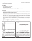
Figure 10-1 shows suggested limits for low impedance reference electrodes.
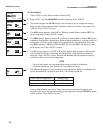
Figure 10-2 shows suggested limits for high impedance glass reference electrodes.
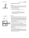
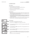
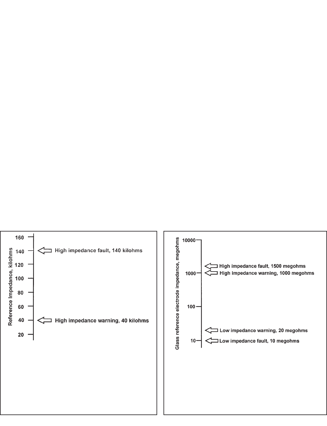
FIGURE 10-1. Suggested Warning and Failure Limits
for Low Impedance Reference Electrodes
The impedance of a typical silver-silver chloride reference
electrode is less than 40 kilohms. If the impedance is greater
than about 140 kilohms the reference electrode has failed.
Failure is usually caused by a plugged or coated reference
junction or a depleted electrolyte fill solution (gel). The refer-
ence impedance will also be high if the sensor is out of the
process liquid.
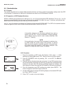
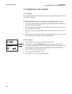
FIGURE 10-2. Suggested Glass Impedance Warning
and Failure Limits for a Glass Reference Electrode
Typical glass impedance is about 100 megohms at 25°C. A bro-
ken or cracked electrode has an impedance of 10 megohms or
less. A glass impedance greater than 1000 megohms suggests
the electrode is nearing the end of its service life. High imped-
ance may also mean the electrode is not immersed in the
process liquid.