


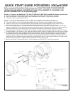

Section 2 Wiring
A. Wire sensor Model 381+-55, 385+-03, or 396P-01-55 directly to the transmitter as shown in Figure 3.
B. Wire sensor Model 381+-52, 385+-04, 396P-02-55, 396P-02-55, or 396R-54 as shown in Figure 4.
C. Wire the 12 - 42.4 Vdc power supply to TB-15 (- 4 - 20 mA) and TB-16 (+ 4 - 20 mA).
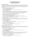
Section 3 Power up and Calibration
A. Apply dc power to the transmitter.
B. Remove the red protective "boot" from the sensor end. Rinse with deionized water and gently pat dry with a tissue (don't
wipe or rub). Place the pH sensor in the first buffer. Install the batteries in the remote controller.
Note: A pH measurement is only as good as the calibration, and the calibration is only as good as the buffers
used. A careful buffer calibration is the first step in making an accurate pH measurement. For best results, cali-
brate with buffers having the same temperature as the process. Allow time for the sensor and buffers to reach the
same temperature. If the process temperature is more than 10
°°
C different from the buffer, allow at least 20 min-
utes. Be careful using buffers at high temperatures because the pH of many buffers is undefined above 60°C. See
the main instruction manual for further information.
C. Aim the infrared remote controller (IRC) at the LCD display.
Press CAL . CALIbrAtE will appear.
Press ENTER . CAL bF1 will appear.
D. With the sensor in the first buffer, be sure the glass bulb and the temperature element are completely submerged (i.e. 3
inches). Do not let the weight of the sensor rest on the glass bulb. Swirl the sensor to dislodge trapped bubbles.
Press ENTER . bF1 will flash until reading is stable. The measured pH value will appear in the main display.
Press
Ï
or
Ð
until the small number next to bF1 matches the nominal pH buffer value (i.e. 4.01 pH).
Press ENTER to save the first calibration point. CAL bF2 will appear.
E. Remove the sensor from the first buffer, rinse, and place in the second buffer.
Press ENTER . bF2 will flash until the reading is stable. The measured pH value will appear in the main display.
Press
Ï
or
Ð
until the small number next to bF2 matches the nominal pH buffer value (i.e. 10.00 pH).
Press ENTER to save the second calibration point.
F. Press RESET to return to the process display. The calibration is complete.
G. Place the sensor in the process. The start up is complete, although the following optional procedure may be useful.
Section 4 Output (OPTIONAL)
A. This optional procedure assigns specific pH values to the 4 - 20 mA output. The factory default is set to 0.00 pH at 4 mA
and 14.00 pH at 20 mA.
Press PROG . OutPut will appear.
Press ENTER . 4 MA will appear. Use the arrow keys to change the displayed number to the desired pH.
Press ENTER to save. 20 MA will appear. Use the arrow keys to change the displayed number to the desired pH.
Press ENTER to save.
Press RESET to return to the process display.
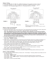
NOTES:
1. INSTRUMENT JUMPER SUPPLIED BY CUSTOMER.
2. DO NOT CONNECT BLUE WIRE INSIDE TRANSMITTER. INSULATE STRIPPED
END OF BLUE WIRE.
FIGURE 3 FIGURE 4