


121
14.2 MEASURING ELECTRODE
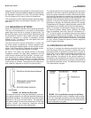
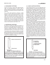
Figure 14-2 shows a typical ORP measuring elec-
trode. The electrode consists of a band or disc of
platinum attached to the base of a sealed glass tube.
A platinum wire welded to the band connects it to the
lead wire.
For a noble metal electrode to develop a stable
potential, a redox couple must be present. A redox
couple is simply two compounds that can be con-
verted into one another by the gain or loss of elec-
trons. Iron (II) and iron (III) are a redox couple. The
oxidized form, iron (III), can be converted into the
reduced form, iron (II), by the gain of one electron.
Similarly, iron (II) can be converted to iron (III) by the
loss of an electron. For more details concerning the
nature of redox potential, see Section 14.5.
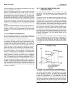
14.3 REFERENCE ELECTRODE
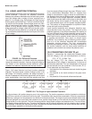
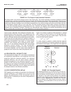
As Figure 14-3 shows, the reference electrode is a
piece of silver wire plated with silver chloride in con-
tact with a concentrated solution of potassium chlo-
ride held in a glass or plastic tube. In many reference
electrodes the solution is an aqueous gel, not a liquid.
The potential of the reference electrode is controlled
by the concentration of chloride in the filling solution.
Because the chloride level is constant, the potential of
the reference electrode is fixed. The potential does
change if the temperature changes.
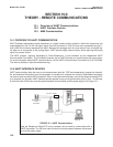
14.4 LIQUID JUNCTION POTENTIAL
A salt bridge (see Figure 14-3) is an integral part of the
reference electrode. It provides the electrical connec-
tion between the reference electrode and the liquid
being measured. Salt bridges take a variety of forms,
anything from a glass frit to a wooden plug. Salt
bridges are highly porous and the pores are filled with
ions. The ions come from the filling solution and the
sample. Some bridges permit only diffusion of ions
through the junction. In other designs, a slow outflow
of filling solution occurs. Migration of ions in the bridge
generates a voltage, called the liquid junction poten-
tial. The liquid junction potential is in series with the
measuring and reference electrode potentials and is
part of the overall cell voltage.
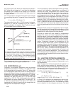
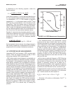
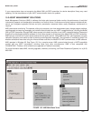
Figure 14-4 helps illustrate how liquid junction poten-
tials originate. The figure shows a section through a
pore in the salt bridge. For simplicity, assume the
bridge connects a solution of potassium chloride and
hydrochloric acid of equal molar concentration. Ions
from the filling solution and ions from the sample dif-
fuse through the pores. Diffusion is driven by concen-
tration differences. Each ion migrates from where its
concentration is high to where its concentration is low.
Because ions move at different rates, a charge sepa-
ration develops. As the charge separation increases,
electrostatic forces cause the faster moving ions to
slow down and the slower moving ions to speed up.
Eventually, the migration rates become equal, and the
system reaches equilibrium. The amount of charge
separation at equilibrium determines the liquid junction
potential.
MODEL 3081 pH/ORP SECTION 14.0
ORP MEASUREMENTS
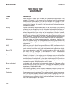
FIGURE 14-2. Measuring Electrode.
An ORP electrode is a piece of noble metal, usual-
ly platinum, but sometimes gold, attached to the
end of a glass tube. The potential of the electrode
is controlled by the ratio of oxidized to reduced sub-
stances in the sample. pH and other constituents in
the sample may also affect ORP.
FIGURE 14-3. Reference Electrode.
The fixed concentration of chloride inside the elec-
trode keeps the potential constant. A porous plug
salt bridge at the bottom of the electrode permits
electrical contact between the reference electrode
and the test solution.