


95
MODEL 3081 pH/ORP SECTION 12.0
TROUBLESHOOTING
12.4.4 rEFWArn
rEF WArn is an electrode fault message. It means the reference electrode impedance exceeds the programmed
Reference Warning High (RWH) limit. Ideally, when the measurement system exceeds the warning limits, the user will
have adequate time to diagnose and correct problems before a failure occurs. A high reference impedance implies that
the liquid junction is plugged or the reference electrolyte is depleted. The message also appears if an inappropriate limit
has been entered into the transmitter.
If the measurement system was previously commissioned and operating correctly, rEF WArn likely means a real problem
exists. However, if the system is being started up or if the advanced diagnostic feature is being used for the first time, rEF
WArn could be caused by a miswired sensor or by programmed limits that are not correct for the sensor.
NOTE
rEF WArn is a sensor diagnostic message. Sensor diagnostic messages
are optional. They can be turned off. To disable sensor diagnostic mes-
sages, refer to Section 8.4.3.
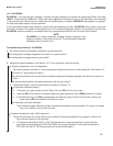
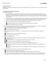
Troubleshooting Flowchart - rEF WArn
Troubleshooting rEF WArn problems is exactly the same as troubleshooting rEF FAIL problems. Refer to Section 12.4.3.
12.4.5 CALIbrAtE
CALIbrAtE is a diagnostic intended for future use. If the CALIbrAtE message is showing go to Section 8.4 and disable
CALIbrAte.
12.4.6 tEMP HI and tEMP LO
tEMP HI and tEMP LO mean the transmitter has detected a problem with the temperature measuring circuit. The problem
may lie in the sensor, the cable, or the transmitter. The determination of temperature is an integral part of the pH meas-
urement. Therefore, failure of the temperature measuring circuit is a system disabling condition. However, in an emer-
gency, automatic temperature compensation can be disabled and the transmitter placed in manual temperature
compensation. Refer to Section 8.5. For manual temperature compensation, choose a temperature equal to the average
temperature of the process. The resulting pH reading will be in error. The more variable the temperature and the further
the pH from 7, the greater the error.
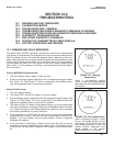
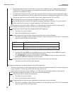
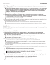
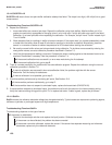
Troubleshooting Flowchart- tEMP HI and tEMP LO
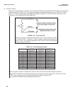
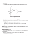
A. Check wiring, jumper settings, and software settings.
1. Check the wiring between the sensor and the transmitter. Refer to the appropriate wiring diagram in Section 3.0.
Pay particular attention to TB-3 (RTD RTN), TB-4 (RTD SN), and TB-5 (RTD RTN). (NOTE: TB-3 means
terminal 3 on the terminal board.)
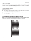
2. Be sure the position of the RTD jumper on the analog board matches the type of RTD in the sensor. See
Section 2.2.
3. Be sure the software settings in Section 8.5 match the type of RTD in the sensor.
If the diagnostic message disappears, the sensor is in good condition.
If the message persists, go to step B.