


97
MODEL 3081 pH/ORP SECTION 12.0
TROUBLESHOOTING
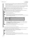
C. Check the transmitter.
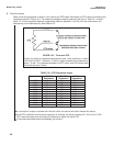
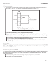
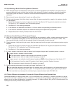
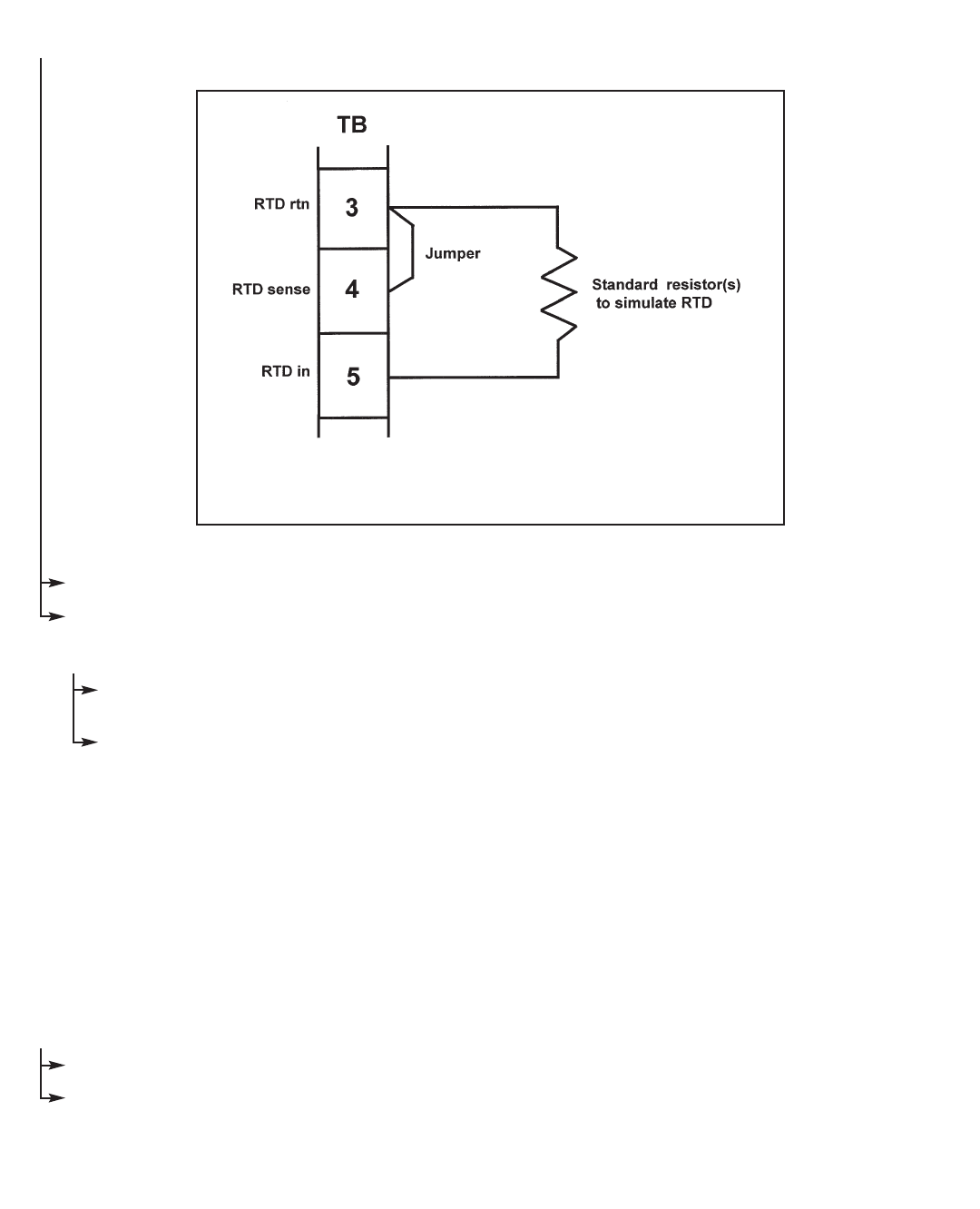
1. Disconnect the RTD sensor leads and wire the circuit shown in Figure 12-4. Set the resistance to the value for
25°C shown in Table 12-1. The measured temperature should equal 25°C to within ±1°C.
If the measured temperature is correct, the transmitter is working properly.
If the measured temperature is incorrect, calibrate the transmitter against the standard resistance equivalent to
25°C. See Section 7.4 for the procedure. Change the resistance and verify that the temperature reading changes
to the correct value.
If the transmitter works properly after temperature calibration, the original calibration was in error. Re-attach
the RTD wires and check the temperature performance of the sensor.
If the reading is still wrong, the transmitter electronics have failed. Replace the electronic board stack
(PN 23574-02).
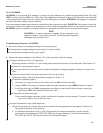
12.4.7 LInE FAIL
LInE FAIL almost always means that the transmitter is measuring an incorrect resistance between terminal TB-3 (RTD
RTN) and TB-4 (RTD SNS). These terminals are critical connections for the three-wire RTD measurement. Figure 12-3
shows a three-wire RTD connection.
Troubleshooting Flowchart- LInE FAIL
A. Check for miswires and open connections at TB-3 and TB-4. Open connections can be caused by loose connections,
poor spade crimps, or broken wires. Be sure to check junction boxes for proper pass through of all wires. See Section
3.0 for junction box wiring.
If correcting a wiring problem makes the message disappear, the system is in good condition.
If the message is still showing go to step B.
FIGURE 12-4. Temperature simulation into
the Model 3081 pH/ORP transmitter.