


111
AW2400 Owner’s Manual
AUX
13
Chapter 13
AUX
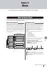
This chapter describes operation of the AW2400 AUX buses.
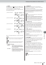
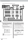
The AW2400 has 4 auxiliary buses that can be assigned to the [OMNI OUT] jacks, the [DIGITAL
STEREO OUT] connectors, or the outputs of an optional I/O card installed in the I/O slot. This
can be useful for sending signals to external signal processing gear, or for monitoring specific
signals within a mix.
Signals from the following channels can be sent to the AUX buses.
• Input channels
•Track channels
• Effect return channels
AUX send levels can be adjusted either by using the graphic knobs in the AUX screen or by using
the Selected Channel section controls.
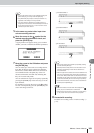
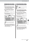
AUX send levels can be adjusted using the graphic knobs
in the AUX screen.
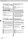
1
Press the Selected Channel section [AUX]
key so that its indicator lights.
The AUX screen will appear.
2
To adjust levels for the AUX1 bus press
Selected Channel knob 1.
The AUX1 screen will appear.
To adjust levels for the AUX2–AUX4 buses press the
corresponding Selected Channel knob (2–4) in the
same way. If the [AUX] key is lit pressing one of the
Selected Channel knobs will take you directly to the
corresponding AUX screen.
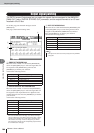
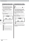
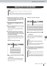
3
Press the Display section [F1] (Input/RTN
page) or [F2] (Track page) key.
The page displays and the items they contain are as
follows.
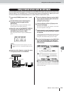
About the AUX buses
• Refer to “Output signal patching” on page 104 for details on assigning the AUX bus outputs.
•AUX 1/2 and 3/4 can be assigned as pairs (
→
p. 58).
HINT
AUX Send Level Adjustment
■ Adjusting AUX send levels via
the AUX screen
• If the AUTO DISPLAY function is set to OFF, press one of the
Selected Channel knobs (1–4) after pressing the [AUX] key
so that its indicator lights. For details about the AUTO DIS-
PLAY function refer to “AW2400 Preferences” on page 210.
NOTE