


EQ/Dynamics Processor Library Operation
Pan, EQ, and Dynamics Processing
155
AW2400 Owner’s Manual
16
3
Press the Display section [F2] key, or press
the [DYN] key as many times as necessary
until the Gate Lib. page appears.
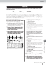
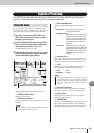
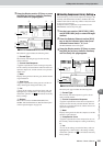
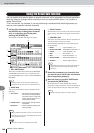
The Gate Lib. page includes the following items.
1 Current Type
The currently selected gate type for the currently
selected channel.
B Current Gate Response
A graphic representation of the current gate response
for the currently selected channel. The horizontal axis
represents input level, and the vertical axis represents
output level.
C Meter
Displays the signal level after the gate, and the amount
of gain reduction.
D Gate Curve
A graphic representation of the gate curve of the cur-
rently selected gate setting in the library list.
E List
A list of all the settings stored in the library. The row
highlighted by a dotted frame is the setting currently
selected for operation. An icon indicates read-only
library settings.
F Buttons
These buttons execute the RENAME, RECALL,
STORE, and CLEAR functions. Detailed description
of their operation begins on page 156.
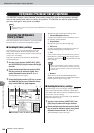
From this library you can recall compressor settings to the
currently selected channel. Of library numbers 001–128,
numbers 001–036 are read-only, and 037–128 can be used
to store your own settings.
Compressor library operations are performed via the
DYNAMICS screen Comp Lib. page.
1
Use the Layer section, [INPUT SEL], [SEL],
and [STEREO SEL] keys to select the target
channel.
2
Press the Selected Channel section [DYN]
key so that its indicator lights, then press
Selected Channel knob 1, 2, 3, or 4.
The DYNAMICS screen will appear.
3
Press the Display section [F4] key, or press
the [DYN] key as many times as necessary
until the Comp Lib. page appears.
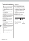
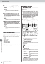
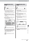
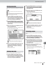
The Comp Lib. page includes the following items.
1 Current Type
The currently selected compressor type for the cur-
rently selected channel.
B Current Compression Response
A graphic representation of the current compression
response for the currently selected channel. The hori-
zontal axis represents input level, and the vertical axis
represents output level.
C Meter
Displays the signal level after the compressor, and the
amount of gain reduction.
D Compression Curve
A graphic representation of the compression curve of
the currently selected compressor setting in the library
list.
E List
A list of all the settings stored in the library. The row
highlighted by a dotted frame is the setting currently
selected for operation. An icon indicates read-only
library settings.
C
B
F
D
A
E
■ Recalling Compressor Library Settings
C
B
F
D
E
A