


AW2400 Owner’s Manual
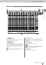
Parts of the AW2400 and what they do
Introducing the AW2400
28
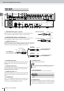
2
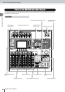
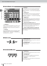
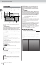
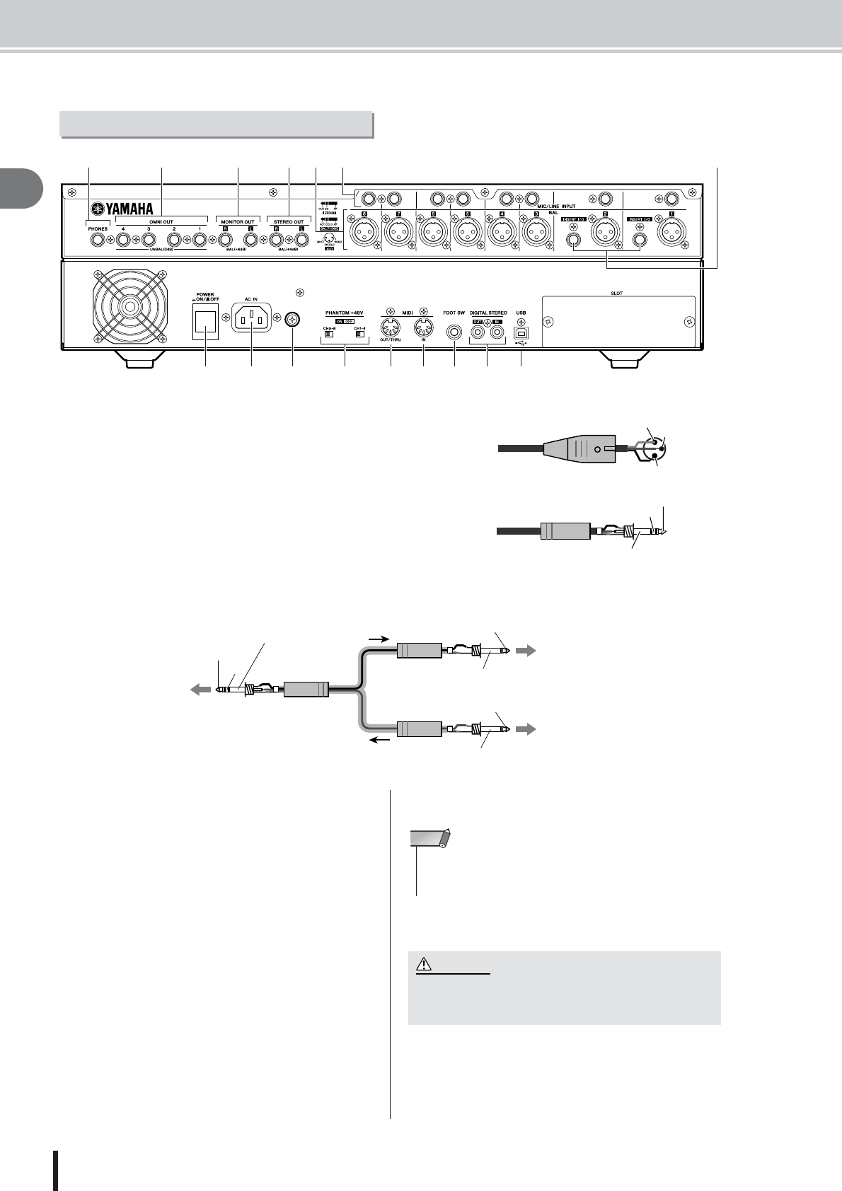
1 [MIC/LINE INPUT] jacks 1–8 (XLR)
These are XLR-3-31 type balanced input jacks. Nominal input level is
from -46 dBu to +4 dBu. Connector wiring is as shown below.
B [MIC/LINE INPUT] jacks 1–8 (TRS phone)
These are TRS phone type balanced input jacks. Nominal input level is
from -46 dBu to +4 dBu. Connector wiring is as shown below.
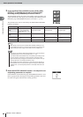
C [INSERT I/O] jacks 1–2
These TRS phone jacks allow external signal processing gear to be inserted
into the signal received at the [MIC/LINE INPUT] jacks 1–2. Nominal
input level is 0 dBu, and the pin assignments are as follows:
D [STEREO OUT] jacks
These are TRS phone type balanced output jacks that out-
put the signals of the stereo bus. Nominal output level is
+4 dBu.
E [MONITOR OUT] jacks
These are TRS phone type balanced output jacks that out-
put the monitor signals of the stereo bus or the solo bus.
Nominal output level is +4 dBu.
F [OMNI OUT] jacks 1–4
The unbalanced phone jacks output the signals specified in
the PATCH screen Output page. Nominal output level is 0
dBu.
G [PHONES] jack
This is a 1/4" TRS phone output jack for connecting your
headphones for monitoring. This jack always outputs the
same signal as the [MONITOR OUT] jacks.
H [POWER] switch
Switches the power ON and OFF.
I [AC IN] connector
Connect the supplied power cord to this connector.
J Ground Screw
For maximum safety the ground screw should be properly
connected to a confirmed ground point. Proper grounding
will also ensure minimum hum, noise, and interference.
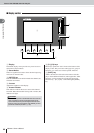
Rear panel
4G EF
H I KJ O P
Q
L M N
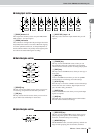
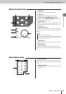
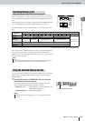
B1C
Male XLR connector
1 (ground)
3 (cold)
2 (hot)
1/4" TRS phone plug
Ring (cold)
Tip (hot)
Sleeve (ground)
OUT
IN
Sleeve (ground)
1/4" TRS
phone plug
1/4" TRS
phone plug
1/4" TRS
phone plug
Tip (OUT)
Sleeve (ground)
Tip (IN)
Sleeve (ground)
To the INSERT I/O
jack of the AW2400
To the input jack of the
external processor
To the output jack of the
external processor
• When switching the power of the AW2400 ON or OFF, always fol-
low the “Turning the power on/off” procedures described on
page 38.
NOTE
• Use only the supplied power cord for this unit. The use of an
inappropriate replacement may be a fire and electrical shock
hazard.
CAUTION