117
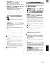
If “L Only” (or “R Only”) is selected, the left and right channels
are linked, and the Limiter is controlled via only the left (or right)
channel.
With “indivi”, the left and right channels control the Limiter indi-
vidually.
: Ratio, : Threshold [dB], : Gain Adjust [dB]
This parameter sets the signal compression “Ratio”. Compression
is applied only when the signal level exceeds the “Threshold”
value.
In the case of the limiter, applying compression will lower the
overall level, so you should use “Gain Adjust” to make adjust-
ments.
: Attack, : Release
These parameters set the attack time and release time. A higher
attack time will cause the compression to be applied more slowly.
: Side PEQ Insert, : Side PEQ Cutoff [Hz], : Q, : Gain [dB]
These parameters are used to set the EQ applied to the trigger sig-
nal.
The Limiter determines whether the compression is applied or
not, based on the post-EQ trigger signal. Setting the equalizer
allows you to set the Limiter to respond to any frequency band.
: Trigger Monitor
Setting this parameter “On” will cause the trigger signal to be out-
put, instead of the effect sound. Use this parameter to check the
trigger signal with EQ applied.
Usually, set this to “Off.”
23: DY3: Multiband Limiter
This effect applies the Limiter to the low range, mid range,
and high range of the input signal. You can control dynamics
for each range to adjust the sound pressure of the low range,
mid range, and high range in a different way from the EQ.
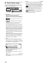
: Low Offset [dB], : Mid Offset [dB], : High Offset [dB]
These parameters set the gain of the trigger signal.
For example, if you do not want to apply compression to the high
range, reduce the “High Offset” value down below the “Thresh-
old” level. In this way, the high range limiter will not respond, and
compression will not be applied.
24: DY4: St.Gate (Stereo Gate)
This effect mutes the input signal if its level is lower than the
specified level. It also reverses the on and off operation of the
gate, and uses Note On and Off messages to turn the gate on
and off.
With “Envelope Select” = “L/R Mix,” the left and right channel
signal mixture will trigger the gate on/off. When “L Only” or “R
Only” is selected, the gate is controlled by either of the channel
signals.
: Polarity
This parameter reverses the Gate on/off operation. With a nega-
tive value, the gate is closed when the input signal level exceeds
the Threshold.
: Attack, : Release
The Attack and Release parameters set the Gate attack time and
release time.
: Delay Time
This parameter sets the delay time of the Gate input. If the sound
has a very fast attack, increase the delay time so that the signal will
be input after the Gate is opened.
25: DY5: St.Exciter/Enhancer
(Stereo Exciter/Enhancer)
This effect is a combination of the Exciter, which adds a punch
to the sound and the Enhancer, which adds spread and pres-
ence.
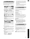
: Exciter Blend
This parameter sets the depth (intensity) of the Exciter effect. Posi-
tive values give a frequency pattern (to be emphasized) different
from negative values.
: Emphatic Point
This parameter sets the frequency to be emphasized. Higher val-
ues will emphasize lower frequencies.
: Enhancer Dly L [msec], : Enhancer Dly R [msec]
These parameters set the delay time for the Enhancer left and right
channel. Specifying a slightly different delay time for the left and
right channel will add a stereo image, depth, and width to the
sound.
26: DY6: St.Decimator (Stereo Decimator)
This effect creates a rough sound like a cheap sampler by low-
ering the sampling frequency and data bit length. You can also
simulate noise unique to a sampler (aliasing).
: Pre LPF
If a sampler with a very low sampling frequency receives very
high-pitched sound that could not be heard during playback, it
could generate pitch noise that is unrelated to the original sound.
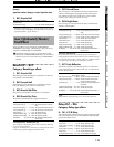
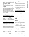
Ratio (Ratio)..................1.0:1...50.0:1, Inf:1 Sets the signal compression ratio
Thrshl (Threshold [dB]).................–40...0dB Sets the level above which the com-
pressor is applied
Attack (Attack)..................................1...100 Sets the attack time
Relse (Release)................................1...100 Sets the release time
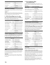
LoOfst (Low Offset [dB])...............–40...0dB Sets the low range gain of trigger signal
MdOfst (Mid Offset [dB])...............–40...0dB Sets the mid range gain of trigger signal
HiOfst (High Offset [dB])...............–40...0dB Sets the high range gain of trigger sig-
nal
GLevel (Gain Adjust [dB]).–Inf, –38...+24dB Sets the output gain
Mix (Wet/Dry) ..............Dry, 1:99...99:1, Wet Sets the balance between the effect
and dry sounds
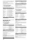
Envelp (Envelope Select)....L/RMix, L Only,
R Only
Selects from Control via the modulation
source, mixing the left and right signals,
Only left, and Only right
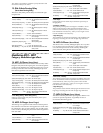
Polrty (Polarity)......................................+, – Switches between non-reversed and
reversed Gate on/off
Thrshl (Threshold)............................0...100 Sets the level to which the Gate is
applied
Attack (Attack)..................................1...100 Sets the attack time
Relse (Release)................................1...100 Sets the release time
DTime (Delay Time [msec])......... 0...100ms Sets the delay time of the gate input
Mix (Wet/Dry) ..............Dry, 1:99...99:1, Wet Sets the balance between the effect
and dry sounds
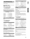
Blend (Exciter Blend)................–100...+100 Sets the intensity (depth) of the Exciter
effect
Empha (Emphatic Point)...................0...140 Sets the frequency to be emphasized
LDly (Enhancer Dly L [msec]).. 0.0...50.0ms Sets the delay time for the Enhancer left
channel
RDly (Enhancer Dly R [msec]) 0.0...50.0ms Sets the delay time for the Enhancer
right channel
*Depth (Enhancer Depth)................... 0...100 Sets the determines to what degree the
Enhancer effect is applied
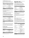
EQTrim (EQ Trim).............................0...100 Sets the 2-band EQ input level
LEQG (Pre LEQ Gain [dB]) –15.0...+15.0dB Sets the gain of Low EQ
HEQG (Pre HEQ Gain [dB])–15.0...+15.0dB Sets the gain of High EQ
Mix (Wet/Dry) ..............Dry, 1:99...99:1, Wet Sets the balance between the effect
and dry sounds
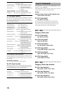
LPF (Pre LPF)..................................Off, On Selects whether the harmonic noise
caused by a decrease in sampling fre-
quency is generated or not
Fs (Sampling Frequency [Hz])...1.0k...44.1k Sets the sampling frequency
Bit (Resolution)...................................4...24 Sets the data bit length
Speed (LFO Frequency [Hz]) .0.02...20.0Hz Sets the LFO speed
*Depth (Depth)...................................0...100 Sets the depth of the sampling fre-
quency modulation
HiDamp (High Damp [%]).................0...100 Sets the ratio of cut of the high range
Level (Output Level) .........................0...100 Sets the output level
Mix (Wet/Dry) ..............Dry, 1:99...99:1, Wet Sets the balance between the effect
and dry sounds
Eff
ec
tIn
s(
2in2
ou
tx2
)/Ms
t
/
Fin
a
l


