11
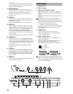
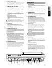
6 [INPUT 3], [INPUT 4] jacks
Mic/line (e.g., keyboard) sources can be input here.
These are balanced 1/4" TRS phone jacks. Unbal-
anced phone jacks can also be connected.
7 [TRIM] knob: –60...–10...+4 dBu
These knobs adjust the input level. The markings
indicate the input level.
Adjust each [TRIM] knob as appropriate for the
input instrument, so that the peak indicator lights
when the connected instrument is played most
loudly.
The input level will depend on the instrument or
performance, but the approximate ranges are as
follows.
–60 – –40 dBu: mic input
–30 dBu: guitar, bass guitar
–10 dBu: consumer audio devices such as a CD
player
+4 dBu: keyboards or studio equipment
If the [TRIM] knob is raised when nothing is con-
nected to an input, hum or noise may result.
8 [PHONES] jack
A set of headphones can be connected here.
This is a 1/4" stereo phone jack.
This outputs the same signal as the [MONITOR
OUT L/R] jacks.
9 [PHONES LEVEL] knob: 0...10
This knob sets the volume level of the headphones.
The volume will increase in correspondence to the
printed gradations.
10 [FOOT SWITCH] jack
When your hands are occupied with playing an
instrument, you can use a foot switch to control
basic operation of the recorder section.
A foot switch can be used to start/stop the play-
back, to start/end manual punch-in recording, to
register a mark, or to record tap tempo. (→p.75)
Connect the foot switch (such as the optional PS-1)
to this jack.
11 [EXPRESSION PEDAL] jack
You can use a pedal to control a specified parame-
ter of an insert effect. You can control the parameter
in realtime while you play or record. (→p.47)
Connect an expression pedal (separately sold
option, EXP-2, XVP-10 etc.) to this jack.
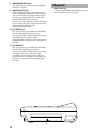
1 [AC 9V] connector
Connect the included AC/AC power supply to this
connector.
2 [MIDI OUT] connector
MIDI messages are transmitted from this connec-
tor. Use this when you wish to control a connected
external MIDI device from the D12. (→p.73)
3 [MIDI IN] connector
MIDI messages are received at this connector. Use
this when you wish to control the D12 from a con-
nected external MIDI device. (→p.73)
4 [LCD CONTRAST] knob
This adjusts the contrast of the LCD screen.
The optimal setting will depend on the viewing
angle, so adjust the contrast as necessary. Looking
from the front panel, turning the knob toward the
right will darken the text, and turning it toward the
left will lighten the text.
5 [SCSI] connector
An external hard disk drive, or removable disk
drive can be connected here, and used for record-
ing/playback in the same way as the internal
drive. An external drive can also be used for
backup. (→p.67)
In addition, a CD-R/RW drive can be connected
here to create an audio CD or to make backups.
(→p.49, 67)
This is a D-Sub half-pitch 50 pin SCSI connector.
For details on the SCSI devices that can be used
with the D12, please refer to the Korg website or
contact Korg dealer.
6 [AUX OUT] jack
This jack outputs the external send signal from
each mixer channel. (The send amount is adjusted
in the [MASTER EFFECT/AUX] “AuxSnd” tab
page.) Connect this jack to your external effect pro-
cessor.
This is a 1/4" phone jack.
7 [MONITOR OUT L/R] jacks
Connect your external monitor system to these
jacks. The bus that is sent to the monitor output is
selected in the [SOLO/MONITOR] “Monitor” tab
page. (→p.109) These jacks output the same audio
signal as [PHONES].
These are RCA phono jacks.
Rear panel
1234 5 1011 9876
Introduction
Panel overview of
the D12


