


11
1. Parts and their functions
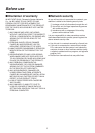
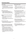
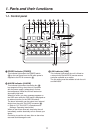
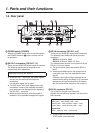
1-1. Control panel
POWER ALARM LINK 3USER 1 4USER 2 SHIFT OSD/TIME OSD ON
PinP ONWIPEMIX
TRANSITION TYPE
KEY-F/SPinPAUX
KEY-S
AUX
PGM
61
PVW
72
KEY OUT
83
CLN
94
MV
A
SHIFT
CUT
AUTO
BKGD
B
SHIFT
KEY-F
PinP
AUX
105
BUS DELEGATION
KEY ON FTB ON
Compact Live Switcher AW-HS50
POWER indicator [POWER]
This indicator lights when the POWER switch
() on the rear panel is set to ON while power is
supplied to the DC IN connector ().
ALARM indicator [ALARM]
This indicator lights when the cooling fan ()
has stopped running, when there is a problem
with the power supply (voltage drop) or when
the temperature inside the unit has reached an
abnormally high level.
When this occurs, an alarm message appears on
the OSD menu while the OSD menu is displayed on
an external monitor (in the OSD ON status).
The alarm information can be output to an external
device from the unit’s TALLY/GPI connector ().
Refer to “5-2. TALLY/GPI” (<Operations and
Settings> Operating Instructions).
When an alarm has occurred, stop using the unit
immediately, and be absolutely sure to contact your
dealer.
Continuing to use the unit even after an alarm has
occurred could damage the unit.
LINK indicator [LINK]
This indicator lights when the unit is linked on
a network with the AW-RP50 remote camera
controller available as an option.
The link setting must be enabled at both the unit
and AW-HS50.