


16
1. Parts and their functions
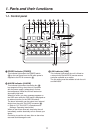
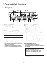
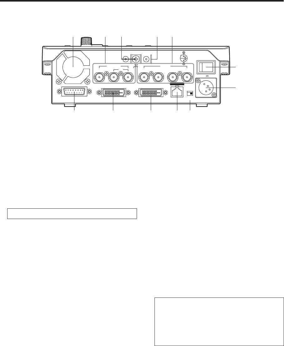
1-2. Rear panel
TALLY / GPI DVI OUT DVI IN
LAN
SDI INSDI OUT
SIGNAL GND
BOOT
POWER
12 V
ON
1
1
2
4
3
234
1
2
IN
SV NM
$"
#
!
POWER switch [POWER]
When the POWER switch is set to the ON position,
the POWER indicator () lights, and the unit can
be operated.
SDI OUT connectors [SDI OUT 1, 2]
These are the HD/SD SDI signal output connectors.
The following signals can be assigned to the
connector by menu operations:
PGM, PVW, CLN, AUX, MV, KEYOUT
At the SDI OUT 1 connector, the output signals
are split into two and output through two
connectors.
It is the same signal that is output.
The OSD menu, multi view display frame, tally
information, names of the materials and audio
level meters are not displayed for the signals of
the SDI OUT 1 connector.
When the high-resolution multi view mode is
enabled, it is not possible to assign MV signals.
SDI IN connectors [SDI IN 1 to 4]
These are the HD/SD SDI signal input connectors.
The following input modes can be set by menu
operations:
SDI IN 1, 2: Normal, DbyD
SDI IN 3, 4: Normal, DbyD, UC, Auto
The video process function can be used for all the
SDI IN 1 to 4 input signals.
The up-converter cannot be used for SDI IN 1
and 2.
When signals differing from the system format
have been input, they are replaced with black
signals.
(However, when HD has been selected as the
system format setting and DbyD or UC has been
selected as the input mode setting, SD signals
with the same vertical frequency can be input.)
DVI IN connector [DVI IN]
This is the DVI-D signal input connector.
Signals with the following resolution can be input to
this connector.
Digital RGB (vertical frequency: 60 Hz):
XGA (1024 768), WXGA (1280 768),
SXGA (1280 1024), WSXGA+ (1680 1050),
UXGA (1600 1200), WUXGA (1920 1200)
Digital RGB:
1920 1080/50p, 1920 1080/59.94p
Analog signals cannot be input to this connector.
A DVI-I cable cannot be used.