24
2. Preparations
2-5. OSD (on-screen display)
menu operations
The unit’s settings are selected using the OSD menus
which are displayed on the external monitor.
Described here is how to operate the OSD menus.
2-5-1. Displaying and clearing the
OSD menus
Basic operations
When the OSD ON button is held down, the OSD ON
button indicator lights, and the OSD menus are
displayed on the external monitor.
When the OSD ON button is held down while an OSD
menu is displayed, the OSD ON button indicator goes
off, and the OSD menu display is cleared.
If parts of the OSD menus overlap the multi
view display frame, the split screen frames and
characters will not be displayed.
Note
Changing the connector for
outputting the OSD menus
15&176 5&+176&8+176
15&5K\G (7..
15&$CEM 1P
-G[2TKQTKV[ 2KP2QXGT-';
$WU/QFG 2)/#256$
6KOG7PKV 5GE
5NKFG.GXGT $-)&
)2++PRWV 'PCDNG
)2+1WVRWV 'PCDNG
%CO%QPV.KPM 1HH
5;56'//GPW 7PNQEMGF
=?1RGTCVKQP/GPW
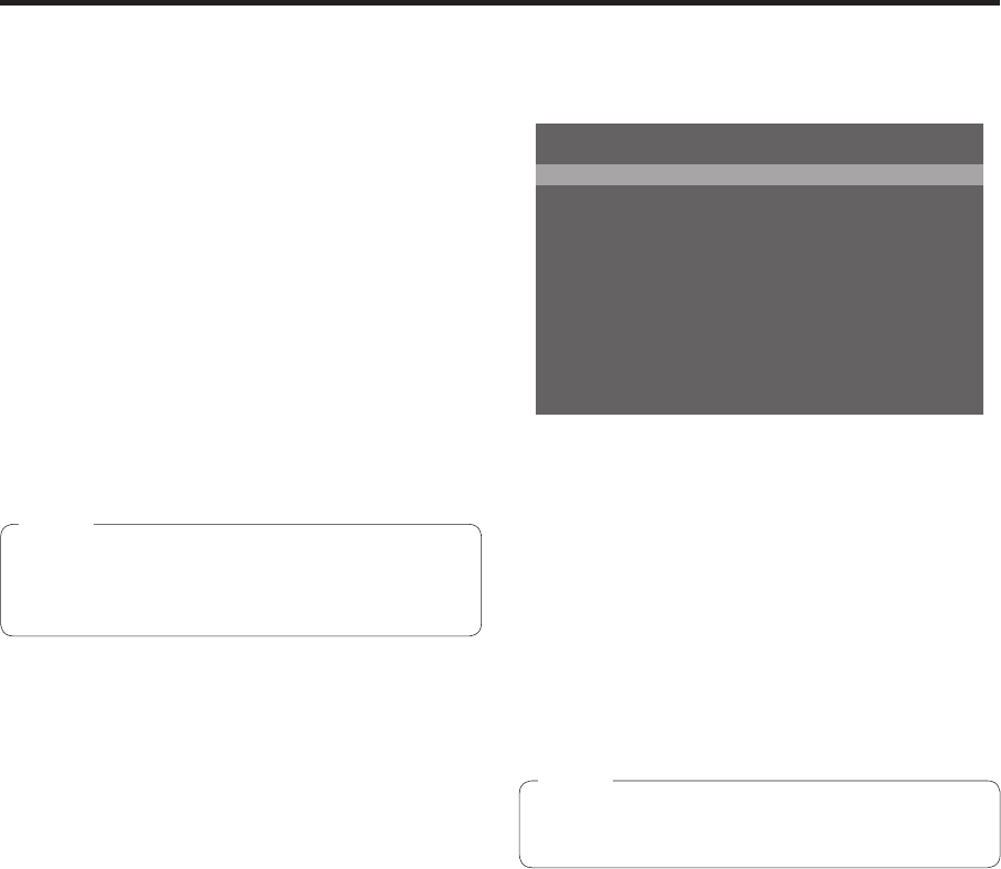
The OSD menu output connector can be changed
using the “1. OSD OUT” item on the [13] Operation
Menu.
SDI-OUT2:
The menus are output from the SDI OUT 2
connector.
DVI-OUT:
The menus are output from the DVI OUT
connector.
SDI-OUT2+DVI-OUT:
The menus are output from both the SDI OUT 2
connector and DVI OUT connector.
The OSD menus cannot be output from the
SDI OUT 1 connector.
Note
2-5-2. How to forcibly display the OSD
menus
When the OSD ON button is held down while holding
down the SHIFT button, the following settings are
established automatically.
The OSD ON button indicator lights, and the OSD
menus are displayed on the external monitor.
The output destination of the OSD menus is set
to both the SDI OUT 2 connector and DVI OUT
connector.
The screen size of the OSD menus output from the
DVI OUT connector is set to Auto.
(The menus are output in the size that corresponds
to the input specifications of the PC monitor which
is connected to the unit.)
