


7
Characteristics
Compact design
p The unit features a compact design with its half-rack
size width (210 mm (8-1/4˝)) and its 4RU size (177 mm
(6-15/16˝)) depth.
The AW-RP50 remote camera controller (option) also has
the same size. When it is placed alongside the unit, the
two units are neatly housed in the full rack width.
Multiple formats supported
p The signal formats supported by the unit include
both HD formats (1080/59.94i, 1080/50i, 1080/24Psf,
1080/23.98Psf, 720/59.94p and 720/50p) and SD formats
(480/59.94i and 576/50i).
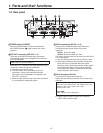
Five input systems and three output systems featured
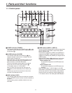
p The unit comes with four SDI input connectors (SDI IN 1
to SDI IN 4) and one DVI-D input connector (DVI IN).
p It also comes with two SDI output connectors (SDI OUT 1
and SDI OUT 2) and one DVI-D output connector
(DVI OUT).
Frame synchronizer system
p A 10-bit frame synchronizer is incorporated for each of
the SDI inputs so that asynchronous video signals can be
selected with no accompanying shocks.
2-channel up-converter, 4-channel Dot by Dot function
and 4-channel video process function
p An up-converter is incorporated in SDI IN 3 and SDI IN 4.
p A Dot by Dot function is incorporated for all the SDI input
connectors (SDI IN 1 to SDI IN 4).
By using this function and the PinP function together,
SD materials can be embedded in HD images with no
deterioration in the image quality.
p The video process function is incorporated in all the
SDI input connectors (SDI IN 1 to SDI IN 4) to make it
possible to adjust the colors at the input stage of the
switcher.
Multi view display function
p One channel is provided for the multi view display
function.
The user can select whether the screen is to be split into
10, 9, 6, 5 or 4 sections.
p On each split screen, the user can assign PGM, PVW,
AUX or other materials in addition to input materials IN1
to IN5.
Many different effect functions provided
p The unit enables the user to select wipe or mix as the
type of background transition.
p A 1-channel keyer function is provided. The user can
select linear keys, luminance keys or chroma keys as the
key type.
p One PinP channel and one AUX bus system are
available.
The user can choose not only cut transitions but also mix
transitions as the effect yielded for switching materials
using the PinP bus and AUX bus. (Bus transition function)
2-channel frame memory (8 bits)
p The user can select the still images stored in the frame
memory as the bus material.
p Still images can be transferred from the host computer,
which is connected to the unit via a LAN, to the frame
memories.
Audio level meter display function
p This function enables the level of the embedded audio
signals transferred by SDI input to be displayed.
Straightforward and flexible operability
p The control panel layout includes a row of five crosspoint
buttons for the A bus and another row of five crosspoint
buttons for the B bus. Using these buttons together with
the SHIFT button enables a total of ten images to be
switched. Cut switches are also made possible by the
CUT button.
p Separate buttons enable the PinP, KEY and FTB
functions to be turned ON or OFF in a single-step action.
p The slide lever is not only used to initiate background
transition operations but it can also be allocated to
execute PinP and KEY fade in/out operations.
p Two USER buttons located on control panel.
Using these buttons together with the SHIFT button
allows a total of four user settings (USER1 to USER4) to
be allocated.
PinP settings or WIPE pattern settings can be allocated
to the USER buttons
On-screen display (OSD)
p The setting menus can be displayed on an external
monitor from the SDI OUT 2 and DVI OUT output
connectors.
(These menus cannot be displayed using the SDI OUT 1
output connector.)