


19
2. Preparations
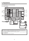
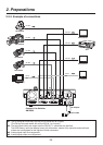
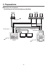
2-2. Connections with other devices
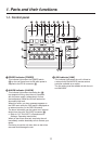
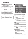
2-2-1. Block diagram
AW-HS50
[Output, 7 pin]
(1) TALLY OUT 1
(2) TALLY OUT 2
(3) TALLY OUT 3
(4) TALLY OUT 4
(5) TALLY OUT 5
(6) ALARM
(7) KEY ON
[Input, 5 pin]
(10) TALLY DISABLE
(11) AUTO
(12) CUT
(13) KEY ON
(14) PinP ON
(15) GND
Hub
AC adapter
Power cable
Output 1, 2
(SDI)
Output 3
(DVI-D)
Scaler
MV
Frame
Audio
Level
Meter
Src
Name
MV
Tally
Scaler
Power
INPUT 1 to 4
(SDI)
INPUT 5
(DVI-D)
TALLY/GPI
(D-sub, 15-pin)
KEY
(LIN, LUM, CHROMA)
BKGD TRANS
(CUT, MIX, WIPE)
PinP
MULTI VIEW
AUX
FTB
BLACK
COLOR
BKGD
COLOR
BAR
FMEM 2
FMEM 1
IN
MTX
SDI IN 1
DbyD
FS
VPrc
SDI IN 2
DbyD
FS
VPrc
SDI IN 3
DbyD
UC
FS
VPrc
SDI IN 4
DbyD
UC
FS
VPrc
FS
DVI IN
OUT
MTX
OSD
DVI OUT
SDI OUT 2
SDI OUT 1
41, 42
LAN
(RJ45)
PC
AW-HE50
AW-RP50
45
44
45
45
43
DC IN
12 V
1: At the SDI OUT 1 connector, the output signals are split into two and output through two connectors.
2: The setting menus (OSD), multi view display frame, tally information, names of the materials and audio
level meters are not displayed for the signals of the SDI OUT 1 connectors.
3: Use a crossover cable when connecting the unit and another device on a 1:1 basis without going through
a hub (switching hub).
4: Use a switching hub.
5: Communication over the internet is not possible.