49
4. Input/output signal settings
4-1. Input signal settings
The SDI IN 1 to SDI IN 4 connectors are the SDI signal input
connectors, and the DVI IN connector is the DVI-D signal
input connector.
The 10-bit frame synchronizer function is enabled for all the
SDI input signals.
Using the frame synchronizer function, it is possible to
switch smoothly between non-synchronized video signals.
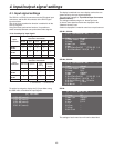
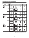
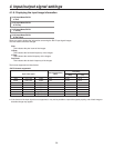
<List of settings by input signal>
Input
connector
Setting menu items and
sections in this manual
MODE
Name
Type
Name
Freeze
Select
Freeze
4.1.1 4.1.2 4.1.3 4.1.4 4.1.5
SDI IN 1,
SDI IN 2
SDI IN 3,
SDI IN 4
DVI IN
—
—
Input
connector
Setting menu items and
sections in this manual
Video Proc UpConv
DVIIn
scaling
DVIIn
information
display
4.1.6 4.1.7 4.1.8 4.1.9
SDI IN 1,
SDI IN 2
—— —
SDI IN 3,
SDI IN 4
——
DVI IN
——
: Can be set; —: cannot be set
To set the input signals, display the [10] Input Menu using
the OSD menu, and select the input signals.
5&++0ZZZZZZ
5&++0ZZZZZZ
5&++0ZZZZZZ
5&++0ZZZZZZ
&8++0ZZZZZZ
=?+PRWV/GPW
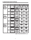
The display is switched to a menu display such as the one
shown below by the input signals selected.
The menu title changes to “Input Menu/Input Connectors
(Material Names)”.
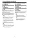
The settings selected using the “4. Name Type” and
“5. Name” items described below are displayed in the
“(Material Names)” area.
A blank is displayed if a material name has not yet been set.
SDI-IN1, SDI-IN2:
/QFG 0QTOCNĄ
(TGG\G5GNGEV (TCOG
(TGG\G 1HHĄ
0COG6[RG &GHCWNV
0COG
82TE;)CKP2GF 1HH^;^2
82TE%)CKP*WG %^*
=?+PRWV/GPW5&++0
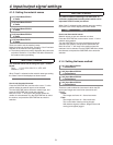
SDI-IN3, SDI-IN4:
/QFG 0QTOCN
(TGG\G5GNGEV (TCOG
(TGG\G 1HHĄ
0COG6[RG &GHCWNV
0COG +0276
82TE;)CKP2GF 1HH^;^2
82TE%)CKP*WG %^*
7%5ECNG'%2QU 553^'%GPVGT
7%5K\G 5
7%/QXFGV
=?+PRWV/GPW5&++0
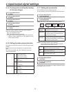
DVI-IN:
(TGG\G 1HH
0COG6[RG &GHCWNV
0COG +0276
5ECNG (KV8
5K\G
*(TGS
8(TGS
&QV%NQEM
=?+PRWV/GPW&8++0
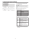
The settings of each menu item will now be described.


