47
3. Basic operations
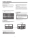
3-9. Frame memories
Still images can be stored in the unit’s two internal frame
memories for use later.
The still images are transferred to the frame memories from
the AUX bus or computer.
p For details on the function for transferring images to
and from a computer, refer to “8. Connections with a
computer”.
The images in the frame memories can be used as bus
images by assigning FMEM1 and FMEM2 in the crosspoint
buttons.
For details, refer to “3-1-3. Assigning signals to the
crosspoint buttons”.
In addition, the frame memory images can be used instead
of the black screen with the FTB (fade to black) function.
The data for the images stored in the frame memories can
be retained even when the power is turned off by saving it in
the flash memory area which is incorporated inside the unit.
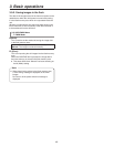
3-9-1. Transferring images from the AUX
bus
The frame memory settings can be selected.
75'4 2KP22TGUGV
75'4 2KP22TGUGV
75'4 2KP22TGUGV
75'4 2KP22TGUGV
(/'/5'.'%6 (/'/
#7:6Q(/'/ 4X1HH^':10
(/'//QFG /#761^':10
=?75'4(/'//GPW
[12] USER/FMEM Menu
5. FMEM Select
Select FMEM1 or FMEM2 as the number of the frame
memory in which to store the images.
[12] USER/FMEM Menu
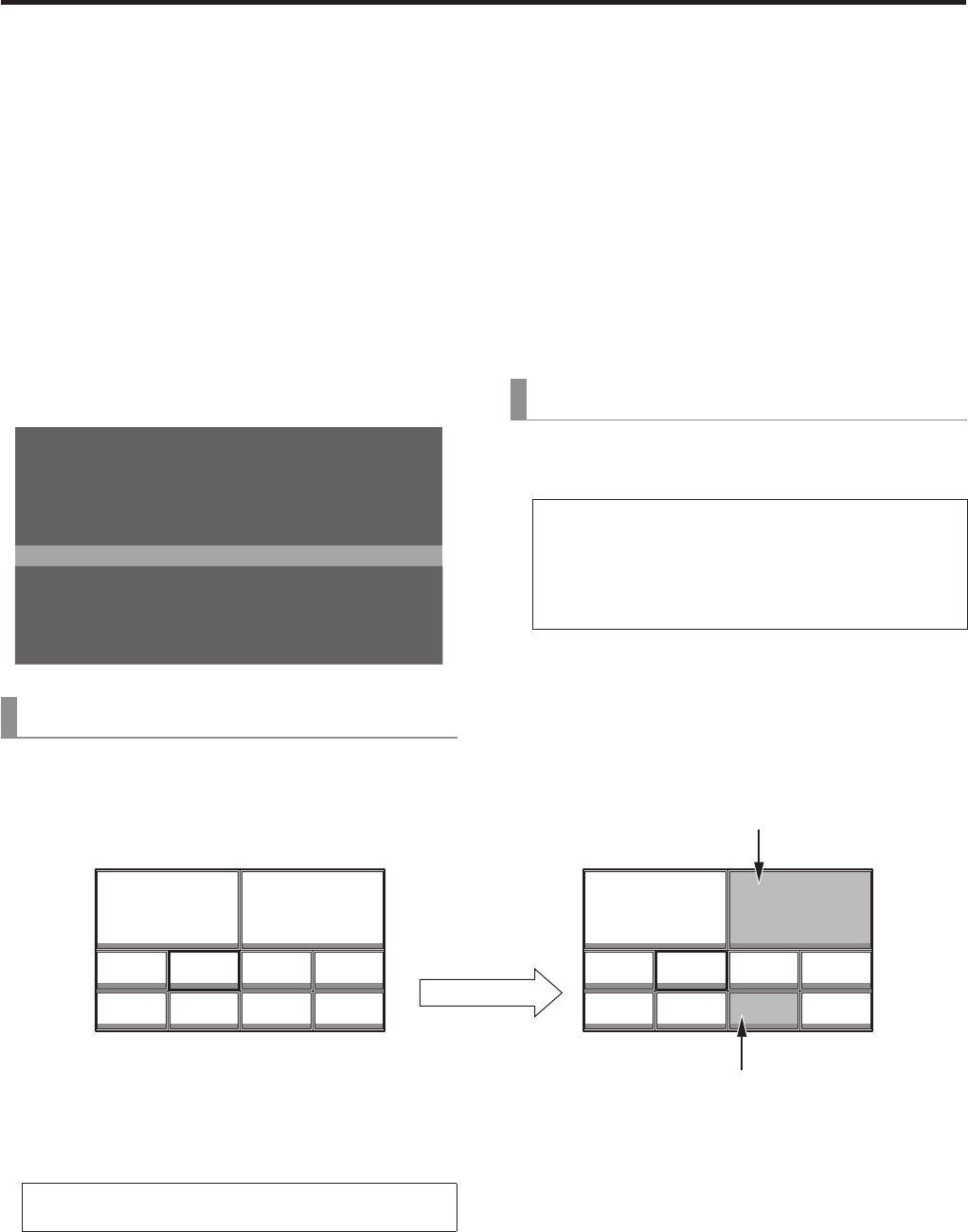
6. AUX to FMEM
Rv (Review):
This setting determines whether the review display is
shown.
On: After an image has been imported, the image in
the frame memory (FMEM1 or FMEM2) selected
for the AUX bus is displayed for about 2 seconds.
Even when the review display appears, the next
image can be imported.
Off: The review display is not shown.
Ex (Exec):
When the OSD/TIME dial is pressed, still images are
imported into the frame memory.
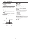
PGM
FMEM1 FMEM2
AUX
PGM
INPUT1 INPUT2 INPUT3 INPUT4
INPUT5 INPUT6 FMEM1 FMEM2
AUX
PGM
FMEM2
AUX
PGM
INPUT1 INPUT2 INPUT3 INPUT4
INPUT5 INPUT6 FMEM1 FMEM2
AUX
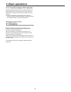
Review display
Imported still image
p Even when MV (multi view display) is selected by the
AUX bus, the following information is not stored in the
frame memory.
Multi view display frame, names of the materials, tally
information, audio level meter


