


Setting Up and Selecting Surround Pan Modes 141
01V96 Version 2—Owner’s Manual
Surround Pan
12
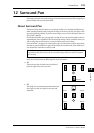
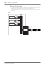
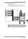
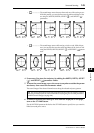
■ Surround Pan Monitoring
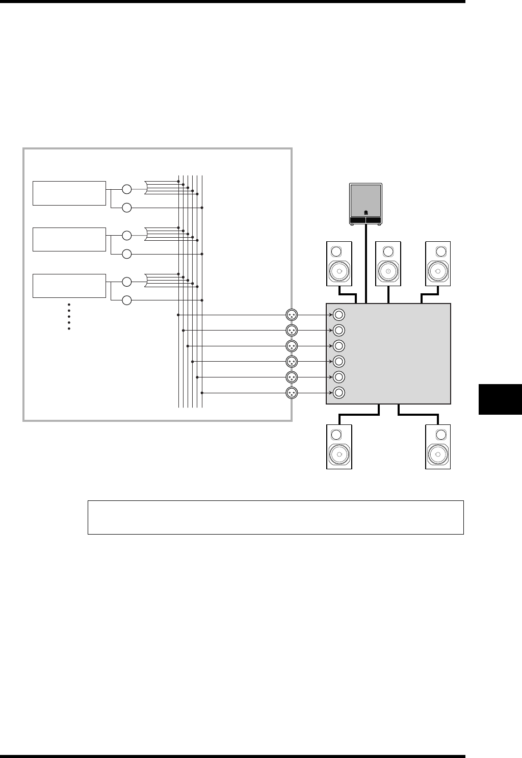
To monitor surround pan movement, patch the Bus Outs to the analog outputs, to which a
monitoring system is connected.
The following diagram illustrates an example in which Bus Out 1 & 2 (left and right front
channel) signals are output from the STEREO OUT L & R connectors and Bus Out 3-6 sig-
nals are output from the OMNI OUT 1-4 connectors in 5.1 Surround mode.
Tip: To output left and right front signals of the surround channels from the STEREO OUT
L & R connectors, turn on the Surround LR to Stereo checkbox on the Surr Bus page.
BUS1 (L)
BUS2 (R)
BUS3 (Ls)
BUS4 (Rs)
BUS5 (C)
BUS6 (LFE)
SURROUND
PA N
LFE LEVEL
SURROUND
PA N
LFE LEVEL
SURROUND
PA N
LFE LEVEL
STEREO OUT L
Front L Front R
Rear L Rear R
Center
Subwoofer
01V96
STEREO OUT R
OMNI OUT 1
OMNI OUT 2
OMNI OUT 3
OMNI OUT 4
Multi-channel
amplifier
Front L
Front R
Rear L
Rear R
Center
Subwoofer
Input Channel 2
Input Channel 1
Input Channel 3