


40 Chapter 4—Connections and Setup
01V96 Version 2—Owner’s Manual
Wordclock Connections and Settings
About Wordclock
Digital audio equipment must be synchronized when digital audio signals are transferred
from one device to another. Even if both devices use identical sampling rates, digital signals
may not transfer correctly, or audible noise or unwanted clicks may occur if the digital
audio processing circuits inside each digital audio device are not synchronized with each
other.
Wo rdclocks are signals that enable digital audio processing circuits to synchronize with each
other. In a typical digital audio system, one device operates as the wordclock master, trans-
mitting wordclock signals, and the other devices operate as wordclock slaves, synchronizing
to the wordclock master.
If you are digitally connecting the 01V96 to other equipment, you must decide which device
to use as the wordclock master and which devices to use as slaves, then set up all the devices
accordingly. The 01V96 can be used as the wordclock master running at either 44.1 kHz, 48
kHz, 88.2 kHz, or 96 kHz, or slaved to an external wordclock source.
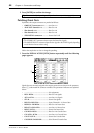
Wordclock Connections
To establish wordclock synchronization between the 01V96 and external devices, you can
distribute wordclock signals independently via dedicated cables, or you can use clock infor-
mation derived from digital audio connections.
The WORD CLOCK IN and OUT connectors transmit and receive wordclock signals inde-
pendently on the 01V96. The following examples show two ways in which wordclock sig-
nals can be distributed and received via the WORD CLOCK IN and OUT connectors.
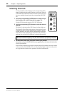
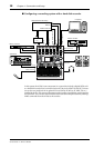
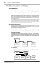
• Daisy Chain Distribution
In this example, the wordclock signal is distributed in a “daisy-chain” fashion, with each
device feeding the wordclock signal from the wordclock out connector on to the wordclock
in connector of the next device. This method of distribution is not recommended for larger
systems.
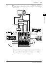
• Star Distribution
In this example, a dedicated wordclock distribution box is used to supply wordclock signals
from the wordclock master to each wordclock slave individually.
WC IN
(BNC)
WC OUT
(BNC)
WC OUT (BNC)
WC IN
(BNC)
WC IN
(BNC)
WC OUT
(BNC)
Wordclock
master
Device A
Wordclock slave
Device B
Wordclock slave
Device C
Wordclock slave
WC OUT
(BNC)
WC IN (BNC) WC IN (BNC) WC IN (BNC) WC IN (BNC)
Wordclock
master
Device A
Wordclock slave
Device B
Wordclock slave
Device D
Wordclock slave
Device C
Wordclock slave
Wordclock
distribution box