


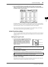
Initial Track Recording 51
01V96 Version 2—Owner’s Manual
5
Tutorial
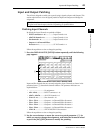
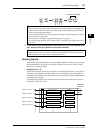
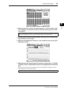
2To cancel a pair, press and hold the [SEL] button for one of the paired chan-
nels, and press the [SEL] button for the other channel.
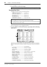
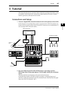
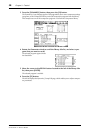
Routing Signals
To record the 01V96 input signals to an external digital multitrack recorder, you must spec-
ify the destination of the signals for each Input Channel. This process is called “routing.”
There are two routing methods.
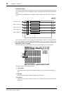
• Using Bus Outs 1–8
Input Channel signals are first routed to Buses 1–8, then through Bus Outs 1–8 to the out-
put connectors or channels. Use this method to mix multiple Input Channel signals and
record them to the MTR’s tracks. If you desire, you can process the signals using the Bus Out
1–8 compressors and EQs.
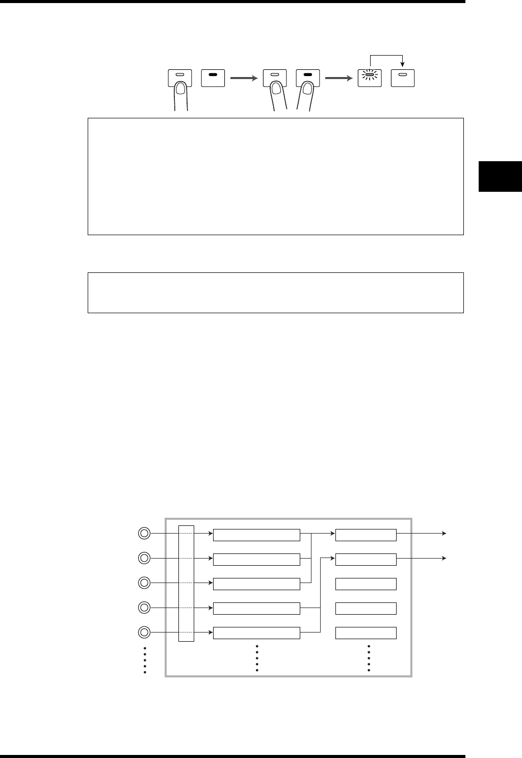
In the following example, Input Channel signals are routed through Bus Outs 1 and 2 to
ADAT OUT connectors 1 and 2.
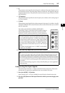
Tip:
•You can still select one of the paired channels for control by pressing the corresponding [SEL]
button. When you select the channel, the [SEL] button indicator lights up, and the [SEL]
button for the paired partner flashes.
•You can also determine how to copy the parameter settings to the paired partner by using a
special window (see page 230).
•You can create or cancel pairs on the Pair/Grup pages (see page 93).
•You can also group the faders, [ON] buttons, EQs, or compressors of multiple channels (see
page 149).
Note: If you want to operate the faders of paired channels, make sure you operate only one
fader for the pair. If you try to operate the faders for both channels in the pair, an excessive
load will be applied to the fader motor, causing malfunction.
SEL SEL SEL SEL SEL SEL
Parameters are copied.
INPUT connector 1
Input Channels 1
CH 1
ADAT OUT
connector
Bus Out 1
INPUT connector 2
Input Channels 2 Bus Out 2
INPUT connector 3
Input Channels 3 Bus Out 3
INPUT connector 4
Input Channels 4
Bus Out 4
INPUT connector 5
Input Channels 5 Bus Out 5
CH 2
Input
Patch