


Selecting Layers 31
01V96 Version 2—Owner’s Manual
3
Operating Basics
Selecting Layers
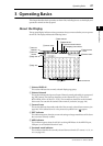
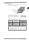
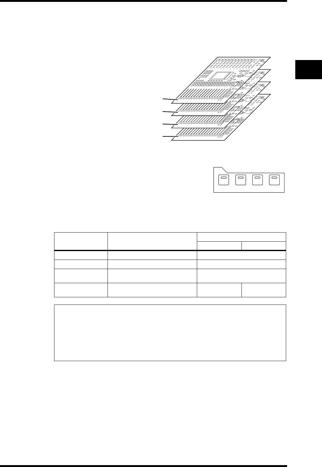
Input Channels and Output Channels (Bus Outs & Aux Outs) are arranged into layers, as
illustrated below. There are four layers altogether.
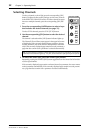
The currently-selected layer determines the function of
the channel strip, [SEL] buttons, [SOLO] buttons,
[ON] buttons, and faders. Use the LAYER buttons to
select a layer you wish to edit using the channel strip
controls.
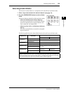
The following table shows the layers that you can access using the LAYER buttons, and the
parameters you can control using the channel strips on each layer.
LAYER buttons Layers
Channel Strips
1–8 9–16
[1–16] button
Input Channel Layer 1–16 Input Channels 1–16
[17–32] button
Input Channel Layer 17–32 Input Channels 17–32
[REMOTE] button
Remote Layer
Operation depends on the selected
target (see page 189).
[MASTER] button
Master Layer
Aux Send masters
1–8
Bus Out masters
1–8
Tip:
• The function of each channel strip fader depends on the currently-selected Fader mode (see
page 33).
• The STEREO [SEL] button, [ON] button, and [STEREO] fader always control the Stereo
Out signal, regardless of the Layer settings.
• The ST IN [SEL] buttons, [SOLO] buttons, [ON] buttons, and level control knobs always
adjust the ST IN channels selected via the [ST IN] button regardless of the Layer settings.
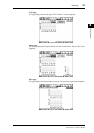
Input Channel Layer 1–16
Input Channel Layer 17–32
Master Layer
Remote Layer
1-16 17-32 MASTER REMOTE
LAYER