


Initial Track Recording 49
01V96 Version 2—Owner’s Manual
5
Tutorial
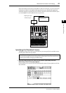
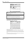
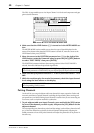
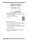
4 Press the [PATCH] button repeatedly until the Patch | Out Patch page
appears. On this page, make sure that the Output Patch settings remain set
to default values, as shown below.
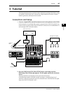
By default (as shown in this example), the signals output from Bus Outs 1–8 are routed to
the ADAT OUT connector (Tracks 1–8 of the hard disk recorder in this example), and to the
slot output channels (Tracks 9–16 of the hard disk recorder in this example).
If the Output Patch settings have been changed from the default settings, recall Output
Patch memory #00 from the Output Patch library (page 175).
Initial Track Recording
This section explains how to make an initial recording to the hard disk recorder’s tracks of
a rhythm machine, synthesizer, bass, guitar, and microphone that are connected to INPUT
connectors 1–12.
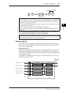
Setting the Input Levels
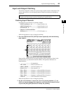
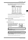
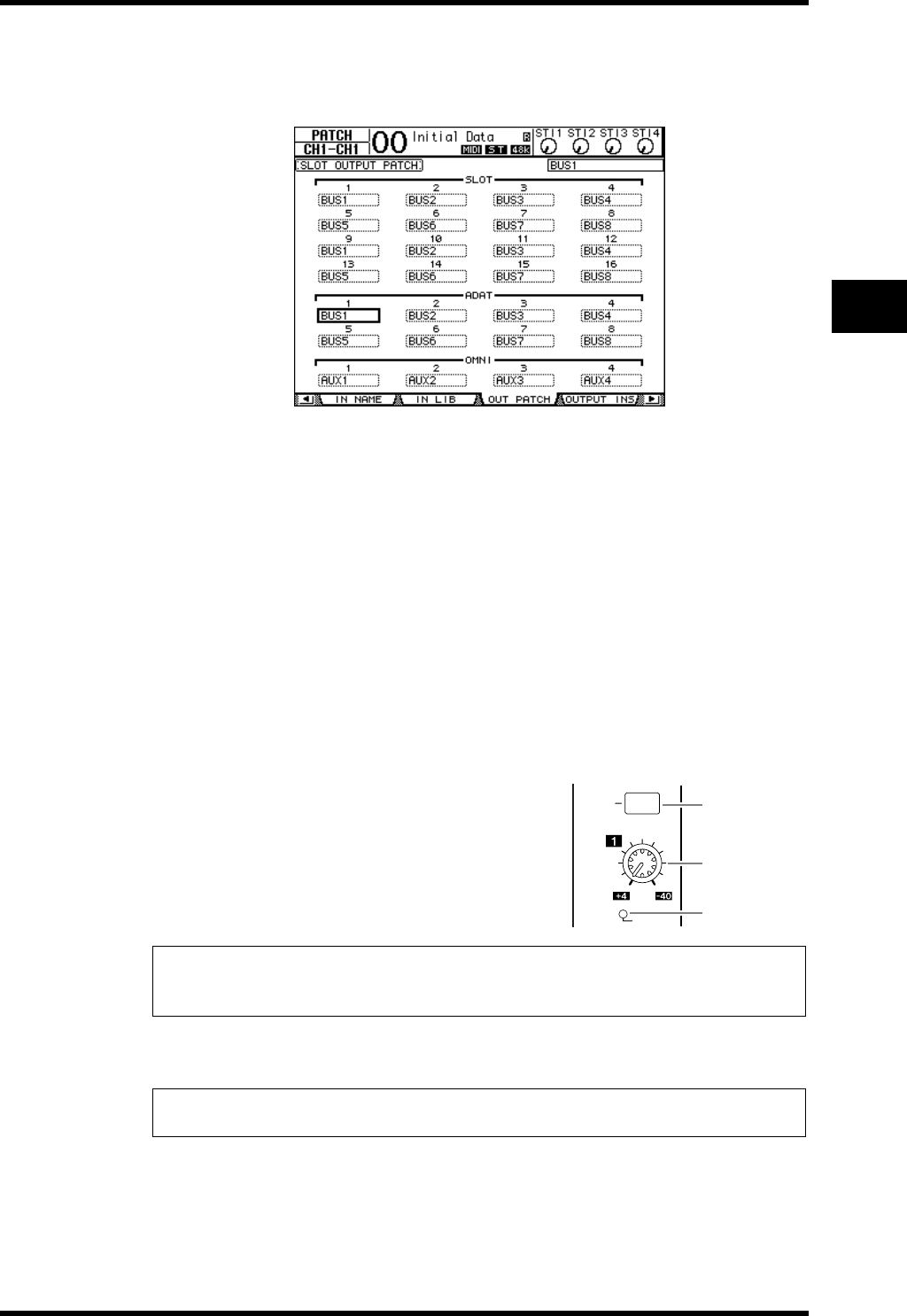
1 Cue the musicians to play the musical instru-
ments connected to INPUT connectors 1–12
while adjusting the corresponding [PAD]
switches and [GAIN] controls so that the
[PEAK] indicators temporarily flash at the
highest volumes.
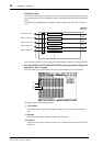
2 Press the LAYER [1–16] button.
Input Channel Layer 1–16 is now available for control from the channel strip section.
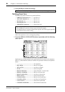
3 Press the FADER MODE [HOME] button, then press the [F1] button to display
the Meter | CH1-32 page.
Meter pages are the start point for mixing and recording. They display channel input and
output levels, and compressor and gate gain reduction amounts.
Tip: The [GAIN] controls adjust the analog input sensitivity. To make a high-quality record-
ing with a wide dynamic range and little noise, set the [GAIN] controls as high as possible
while avoiding clipping.
Tip: Since the fader and [ON] button positions of each layer are memorized, those positions
for the corresponding layer are restored when you switch to that layer.
20dB
GAIN
-16
-60
PAD
PEAK
[PAD] switch
[GAIN] control
[PEAK] indicator