


142
MOTIF Reference
Voice Edit mode
Reference Voice mode
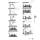
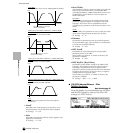
Dual BEF
A combination of two sets of –6dB/oct BEF in parallel.
L
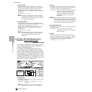
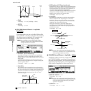
PF12 (Low Pass Filter 12dB/oct)+ HPF12 (High
Pass Filter)
A combination of a LPF and HPF.
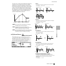
LPF12 (Lo
w Pass Filter 12dB/oct)+ BPF6 (Band Pass
Filter)
A combination of a LPF and BPF.
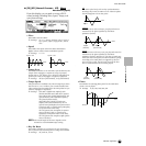
HPF12 (High P
ass Filter 12dB/oct)+ BPF6 (Band Pass
Filter)
A combination of a HPF and BPF.
thru
The filters are bypassed and the entire signal is
unaffected.
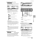
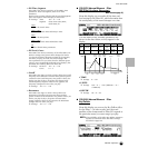
• Cutoff
Determines the cutoff frequency for the Filter, or the
central frequency around which the Filter is applied.
❏ Settings 0 ~ 255
• Gain
Determines the Gain (the amount of boost applied to the
signal sent to the Filter).
❏ Settings 0 ~ 255
•Reso/Width
This parameter’s function varies according to the selected
Filter Type. If the selected filter is an LPF, HPF, BPF
(excluding the BPFw), or BEF, this parameter is used to set
the Resonance. For the BPFw, it is used to adjust the
Width of the band.
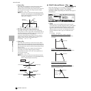
R
esonance
This parameter is used to set the amount of Resonance
(harmonic emphasis) applied to the signal at the cutoff
frequency. This can be used in combination with the
cutoff frequency parameter to add further character to the
sound.
Width
With the BPFw, this parameter is used to adjust the width
of the band of signal frequencies passed by the filter.
❏ Settings 0 ~ 31
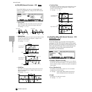
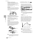
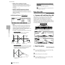
• Distance
Determines the distance between the Cutoff frequencies,
for the Dual Filter types. (The two filters in a combination
are connected in parallel fashion.)
❏ Settings 0 ~ 255
• HPF Cutoff
Determines the central frequency for the Key Follow
parameter (below) of the HPF.
When a filter type “LPF12” or “LPF6” is selected, this
parameter is available.
❏ Settings 0 ~ 255
• HPF KeyFlw (Key Follow)
Determines the Key Follow setting for the HPF Cutoff
frequency. This parameter varies the center frequency
according to the position of the notes played on the
keyboard. A positive setting will raise the center frequency
for higher notes and lower it for lower notes. A negative
setting will have the opposite effect.
When a filter type “LPF12” or “LPF6” is selected, this
parameter is available.
❏ Settings -200% ~ 0 ~ +200%
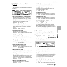
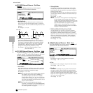
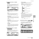
● [F3]-[SF2] Normal Element Filter
Velocity Sensitivity
Basic Structure (page 47)
From this display you can determine how the Filter
and the FEG respond to velocity. (For Filter EG
settings, see “FEG” below.)
Level
Frequency
Distance
The cutoff frequency can be set
directly on the display.
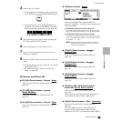
Level
Frequency
Distance
The cutoff frequency can be set
directly on the display.
Level
Frequency
Level
Frequency