


150
MOTIF Reference
Voice Edit mode
Reference Voice mode
● [F6]-[SF2], [SF3], [SF4], [SF5] Drum Common
Effect Parameter Insertion 1, 2, Reverb,
Chorus
The number of parameters and values available
differs depending on the currently selected effect
type. For more information, see the Effect Type List
in the separate Data List booklet.
■ Drum Key Edit
● [F1]-[SF1] Drum Key Oscillator Wave
From this display you can select the desired wave or
Normal voice used for the individual Drum key.
• Type
Determines whether a Wave or a Normal voice is to be
used for the selected key. Also, use the Bank, Number and
Category parameters below to specify the desired Wave or
Normal voice.
❏ Settings pre wave (Preset wave), voice, usr wave
(User wave)
n When the Type is set to
“voice” here, some
parameters in the Drum Voice Edit mode cannot be
edited.
• ElementSw (Element Switch)
This parameter is available when Type (above) is set to
“pre wave” or “user wave.” This determines whether the
currently selected key is on or off, or in other words,
whether the wave for the key is active or inactive.
❏ Settings on, off
• Bank
This parameter is available when Type (above) is set to
“voice.” Any of the Normal voice banks can be selected.
n Plug-in voices cannot be selected for Drum keys.
• Number
Determines the Wave/Voice number. The number differs
depending on the selected Type.
❏ Settings
When Type is set to “pre wave”: 001 ~ 1309
When Type is set to “voice”: 001 ~ 128
When Type is set to “usr wave”: 001 ~ 256
For more information about available Waves and
Voices, refer to the separate Data List booklet.
• Category
Determines the Category of the Wave/Normal Voice. If you
switch to another Category, the first Wave/Normal Voice
in that Category will be selected.
❏ Settings For more information about the Categories,
refer to the separate Data List booklet.
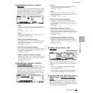
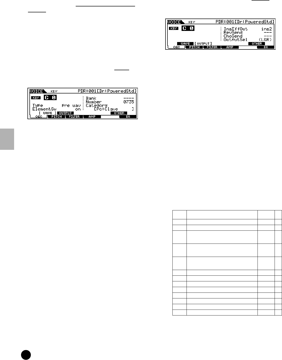
● [F1]-[SF2] Drum Key Oscillator Output
From this display you can set certain output
parameters for the selected Drum key.
• InsEFOut (Insertion Effect Output)
Determines which Insertion effect (1 or 2) is used to
process each individual Drum key. The “thru” setting lets
you bypass the Insertion effects for the specific key.
❏ Settings thru, ins1 (Insertion Effect 1), ins2
(Insertion Effect 2)
•RevSend (Reverb Send)
Determines the level of the Drum key sound (the bypassed
signal) that is sent to Reverb effect. A setting of “0” results
in no Reverb processing of the Drum key sound. This is
available only when Insertion Effect Output (above) is set
to “thru.”
❏ Settings 0 ~ 127
• ChoSend (Chorus Send)
Determines the level of the Drum key sound (the bypassed
signal) that is sent to Chorus effect. A setting of “0” results
in no Chorus processing of the Drum key sound. This is
available only when Insertion Effect Output (above) is set
to “thru.”
❏ Settings 0 ~ 127
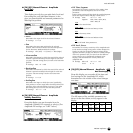
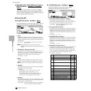
• OutputSel (Output Select)
Determines the specific output(s) for the individual Drum
key signal. You can assign each individual Drum key
sound to be output from a specific hardware output jack
on the rear panel. By installing the optional AIEB2 board,
you can expand the number of assignable outputs.
❏ Settings See below.
* Available only when the optional AIEB2 board has been installed.
LCD Output jacks
Stereo/
Mono
L&R OUTPUT L and R Stereo
asL&R ASSIGNABLE OUTPUT L and R Stereo
as1&2 ASSIGNABLE OUTPUT 1 and 2 on the AIEB2 Stereo
1 : L
2 : R
*
as3&4 ASSIGNABLE OUTPUT 3 and 4 on the AIEB2 Stereo
3 : L
4 : R
*
as5&6 ASSIGNABLE OUTPUT 5 and 6 on the AIEB2 Stereo
5 : L
6 : R
*
asL ASSIGNABLE OUTPUT L Mono
asR ASSIGNABLE OUTPUT R Mono
as1 ASSIGNABLE OUTPUT 1 on the AIEB2 Mono *
as2 ASSIGNABLE OUTPUT 2 on the AIEB2 Mono *
as3 ASSIGNABLE OUTPUT 3 on the AIEB2 Mono *
as4 ASSIGNABLE OUTPUT 4 on the AIEB2 Mono *
as5 ASSIGNABLE OUTPUT 5 on the AIEB2 Mono *
as6 ASSIGNABLE OUTPUT 6 on the AIEB2 Mono *