


41
MOTIF Basic Structure
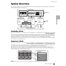
System Overview
Basic Structure
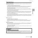
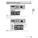
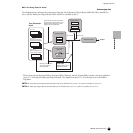
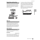
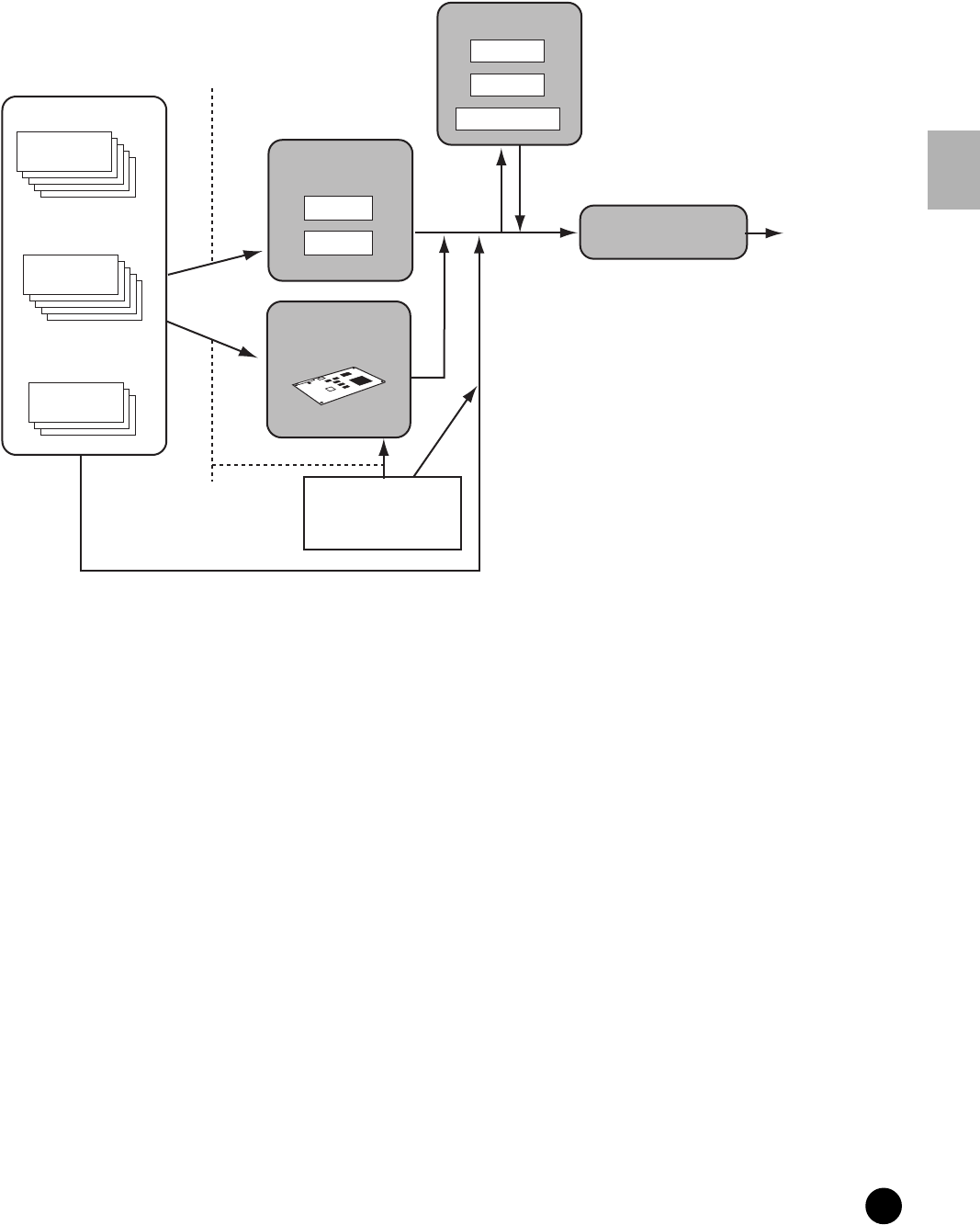
● In the Song/Pattern mode:
Reference (page 210)
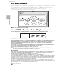
The diagram below indicates the connection when the Vocal Harmony Plug-in Board (PLG100-VH) is installed to
slot 1 and the Multi part Plug-in Board (PLG-100XG) is installed to slot 3.
* Please note that the Insertion Effect, Insertion Effect (Plug-in), and the System Effect cannot cannot be applied to
parts 17~32 (using the Multi-part Plug-in board). The signal from parts 17~32 is directly sent to the Master
Equalizer.
n The Vocal Harmony Plug-in Board (PLG100-VH) can be installed only to slot 1. It cannot be installed to slot 2 or 3.
n The Multi part Plug-in Board (PLG100-XG) can be installed only to slot 3. It cannot be installed to slot 1 or 2.
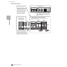
Part 17-32 *
(When the Multi-part Plug-
in board has been installed)
Plug-in Part 2
(When the Single part Plug-
in board has been installed)
Part 1~16
Tone Generator
block
A/D Input
• External audio source
• Microphone sound
Select the part to which the Insertion
effect is applied. The connection type
depends on the setting of the Voice
assigned to the selected part.
Select the part to which
the Plug-in Insertion
effect is applied.
Return Level
Send Level
Output
System Effect
Reverb
Chorus
Variation
Insertion Effect
PLG100-VH
Insertion Effect
(Plug-in)
1
2
Master Equalizer