


173
MOTIF Reference
Performance Edit mode
Reference Performance mode
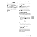
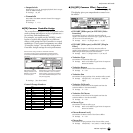
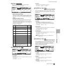
● [F3] Part Output Select
From this display you can set certain output
parameters for the selected part.
• InsEF (Insertion Effect)
This shows whether the Insertion effect is applied or not
for each part. This is for display purposes only and cannot
be set here. To set this, see “EF PART” (Effect Part) on
page 40.
• OutputSel (Output Select)
Determines the specific output(s) for the individual part.
You can assign each individual part’s voice to be output
from a specific hardware output jack on the rear panel. By
installing the optional AIEB2 board, you can expand the
number of assignable outputs.
❏ Settings See below.
*Available only when the optional AIEB2 board has been installed.
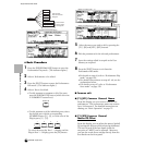
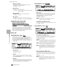
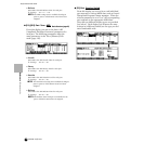
● [F4]-[SF1] Part Tone Tune
• NoteShift
Determines the pitch (key transpose) setting for each part
in semitones.
❏ Settings -24~+24
• Detune
Determines the fine tuning for each part.
❏ Settings -12.8Hz ~+12.7Hz
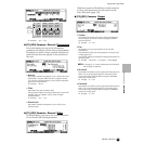
● [F4]-[SF2] Part Tone Filter
Basic Structure (page 46)
From this display you can set various Filter related
settings, to change the tonal qualities of the selected
part’s voice.
• Cutoff
Determines the cutoff frequency for each part.
This parameter is available for the LPF when the filter
used by the part is a combination type of LPF and HPF.
❏ Settings -64 ~ 0 ~ +63
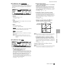
• Resonance
Determines the amount of filter resonance or emphasis of
the Cutoff Frequency for each part.
❏ Settings -64 ~ 0 ~ +63
• FEG Depth
Determines the Filter Envelope Generator depth (amount
of Cuttoff frequency) for each part.
❏ Settings 0 ~ 127
n The FEG Depth setting is not available for the
Plug-in parts.
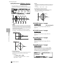
● [F4]-[SF3] Part Tone FEG
Basic Structure (page 47)
From this display you can set the FEG (Filter Envelope
Generator) parameters for each part. The following
parameters offset the same parameters in the Voice
(Element) Edit mode (page 142).
• Attack
Determines the FEG Attack Time for each part.
❏ Settings -64 ~ 0 ~ +63
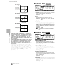
• Decay
Determines the FEG Decay Time for each part.
❏ Settings -64 ~ 0 ~ +63
• Sustain
Determines the FEG Sustain Level for each part.
❏ Settings -64 ~ 0 ~ +63
LCD Output jacks
Stereo/
Mono
L&R OUTPUT L and R Stereo
asL&R ASSIGNABLE OUTPUT L and R Stereo
as1&2 ASSIGNABLE OUTPUT 1 and 2 on the AIEB2
Stereo
1 : L
2 : R
*
as3&4 ASSIGNABLE OUTPUT 3 and 4 on the AIEB2
Stereo
3 : L
4 : R
*
as5&6 ASSIGNABLE OUTPUT 5 and 6 on the AIEB2
Stereo
5 : L
6: R
*
asL ASSIGNABLE OUTPUT L Mono
asR ASSIGNABLE OUTPUT R Mono
as1 ASSIGNABLE OUTPUT 1 on the AIEB2 Mono *
as2 ASSIGNABLE OUTPUT 2 on the AIEB2 Mono *
as3 ASSIGNABLE OUTPUT 3 on the AIEB2 Mono *
as4 ASSIGNABLE OUTPUT 4 on the AIEB2 Mono *
as5 ASSIGNABLE OUTPUT 5 on the AIEB2 Mono *
as6 ASSIGNABLE OUTPUT 6 on the AIEB2 Mono *
drum
This setting is for Drum voice parts. When this is
selected, the output destination settings for each
Drum key (made in Drum Key Oscillator Output,
page 149) are enabled.
Mono