


283
MOTIF Appendix
Installing Optional Hardware
Appendix
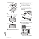
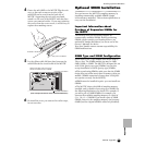
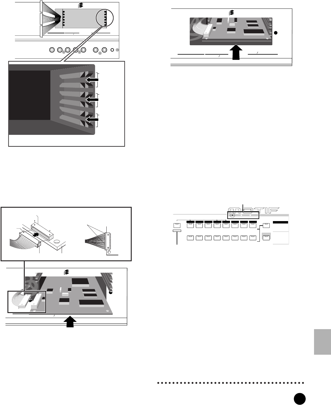
4 Insert the board along the guide rails about two-
thirds of the way inside the MOTIF, with the
connector side face up and toward you.
5 With the board still protruding slightly from the
expansion bay, bring the cable end around and
connect it to the board. Make sure to connect the
proper cable, matching the color of the cable to the
slot used. Also, take care not to pull on the cable
too forcefully as you connect it to the board.
n The Vocal Harmony Plug-in board (PLG100-VH) can
installed only to slot 1.
n The Multi part Plug-in board (PLG-100XG) can installed
only to slot 3.
6 Insert the Plug-in board the rest of the way into
the expansion bay. Carefully put the the ribbon
cable back into the MOTIF, making sure that no
part of the cable sticks out of the instrument.
7 Replace the cover with the screw you removed in
step 2 above. The Plug-in board is held in place by
replacing the cover.
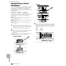
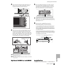
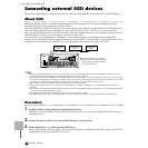
8 Check that the installed Plug-in board is
functioning properly. Turn on the power.
• A message appears indicating that the installed Plug-in
Board is being checked. The main display then appears
and the corresponding slot indicator at the right top of the
front panel lights. This indicates that the board has been
successfully installed.
• If an error message appears, the MOTIF freezes after a
while, indicating that the installation was not successful. If
this happens, turn off the power and carefully go through
the installation procedure again.
Optional AIEB2 or mLAN8E Installation
OUTPUT
ASSIGNABLE
OUTPUT
L MONO
PHONES
A
D INPUT
GAIN
RL
R
R
L
GREEN
YELLOW
ORANGE
3
2
1
Plug-in SLOT
Slot 3
Slot 2
Slot 1
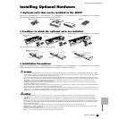
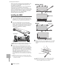
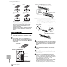
Securely insert the board into the appropriate slot,
taking care that the board isn't jammed between slots.
OUTPUT
ASSIGNABLE
OUTPUT
L MONO
PHONES
A
D
INPUT
GAIN
RL
R
R
L
GREEN
YELLOW
ORANGE
3
2
1
Plug-in SLOT
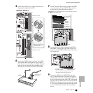
Notch
Connector from MOTIF
Plug-in Connector
Press the connectors together
until the two notches lock into
the sockets.
Plug-in board
OUTPUT
ASSIGNABLE
OUTPUT
L MONO
PHONES
A
D
INPUT
GAIN
RL
R
R
L
GREEN
YELLOW
ORANGE
3
2
1
Plug-in SLOT
PLG 2
A
B
C
D
E
F
G
H
CATEGORY
SEARCH
MUSIC
PRODUCTION
SYNTHESIZER
Integrated
Sampling
Sequencer
Real-time External Control
Surface
Modular
Synthesis
Plug-in
System
DRUM KITS
FAVORITES
SLOT 1 SLOT 2 SLOT 3
PRE 1
PRE 2
PRE 3
GM
USER PLG 1
PLG 3
A. PIANO
KEYBOARD
ORGAN
GUITAR/
PLUCKED
BASS
STRINGS
BRASS
REED/PIPE
SYN LEAD SYN PAD/
CHOIR
SYN COMP CHROMATIC
PERCUSSION
DRUM /
PERCUSSION
SE
MUSICAL FX COMBI
SECTION
BANK
GROUP
COMMON
Slot indicator lamps
In this example, a Plug-in board has been installed to slot 1.