


M7CL Owner’s Manual
Changing the output patch settings
106
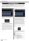
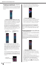
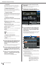
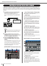
1
Icon button
This indicates the icon selected for that channel.
When you press this button, a screen will appear in
which you can select an icon or sample name.
B
Channel name input box
This indicates the name assigned to that channel.
When you press this field, a keyboard window allow-
ing you to assign a name will appear.
C
Output port button
This indicates the currently selected output port. If you
press this button when selecting an icon or changing
the channel name, you will return to the output port
select screen.
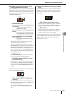
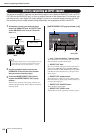
D
Output port select tabs
These tabs select the output ports shown in the popup
window. Each tab corresponds to the following output
ports.
●
OMNI/2TR OUT (M7CL-32/48)
OMNI OUT jacks 1–16 and the 2TR OUT DIGITAL
jack will be displayed.
●
ES/2TR OUT (M7CL-48ES)
EtherSound output channels 1–24 and the 2TR OUT
DIGITAL jack will be displayed.
●
SLOT 1–SLOT 3
Output channels 1–16 of slots 1–3 will be displayed.
●
RACK
The input ports of rack 1–8 will be displayed.
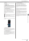
E
Output port select buttons
These buttons assign an output port to the currently
selected output channel.
F
Tabs
Use these tabs to switch between items.
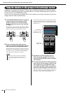
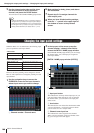
3
Use the output port select tabs and the out-
put port select buttons to specify the out-
put port that will be assigned to that
channel.
If the output port select buttons are not shown at the
bottom of the window, press the PATCH tab.
4
Use the navigation keys and the [SEL] keys
to switch the output channels being con-
trolled, and specify their output ports in the
same way.
5
When you have finished making settings,
press the “
×
” symbol located in the upper
right to close the window.
You will return to the OVERVIEW screen.
●
Selecting the output channel for each
output port
Here’s how you can select the output channel that will be
the output source for each output port.
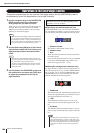
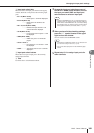
1
In the function access area, press the
SETUP button to access the SETUP screen.
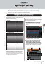
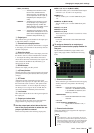
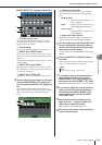
2
In the SYSTEM SETUP field located in the
center of the screen, press the OUTPORT
SETUP button to open the OUTPUT PORT
popup window.
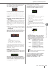
In the OUTPUT PORT popup window you can assign
the source channel for each output port. The popup
window includes the following items.
1
Slot number / Card type
If an output channel of slot 1–3 is selected for opera-
tions, this shows the slot number and the type of I/O
card installed in that slot.
B
DELAY SCALE field
Here you can select the units for the delay time shown
below the delay time knob (
5
).
• METER (343.59m/s)
........... The delay time is shown as a dis-
tance in meters, calculated as the
speed of sound (343.59 m/s) at an
air temperature of 20
°
C (68
°
F)
multiplied by the delay time (sec-
onds).
•For details on the GEQ, refer to p. 175.
HINT
OUTPORT SETUP button
1
3
5
6
8
J
7
9
4
2