


Operating the Cue function
M7CL Owner’s Manual
Monitor/Cue
13
159
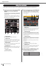
• DCA TRIM knob
...........Adjusts the level of cue output from
a DCA group in a range of -20 dB–
+10 dB. You can operate this knob
using multifunction encoder 4.
• DCA UNITY button
...........If this button is on, pressing the
[CUE] key of a DCA group will
always monitor the corresponding
DCA group at unity gain (the same
level at when the fader in the Centr-
alogic section is at 0 dB).
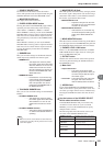
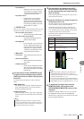
D OUTPUT field
Here you can select one of the following choices as the
position from which output channels will be cued.
• PFL (Pre-Fader Listen) button
...........The pre-fader signal will be output
• AFL (After-Fader Listen) button
...........The signal immediately after the
[ON] key will be output
• PFL TRIM knob
...........If you select PFL, you can also use
the PFL TRIM knob located in the
lower part of this field to adjust the
output level in a range of -20 dB–
+10 dB. You can operate this knob
using multifunction encoder 5.
E Meter field
•Level meter....This indicates the level of the cue
signal.
•ACTIVE CUE indicator
...........This indicates the currently-active
Cue group.
• CLEAR CUE button
...........Clears all Cue selections. This oper-
ation can also be performed using
the CLEAR CUE button in the MON-
ITOR screen.
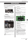
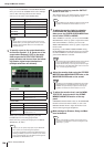
3
Use the buttons of the CUE MODE section
to specify what will happen when multiple
[CUE] keys within the same CUE group are
turned on.
Use the following two buttons to choose the Cue
mode.
● MIX CUE button
All channels or DCA groups within the same Cue
group whose [CUE] key is on will be mixed for
monitoring (MIX CUE mode).
● LAST CUE button
Only the channel or DCA group whose [CUE] key
was last turned on will be monitored (LAST CUE
mode).
4
Use the buttons and knobs of the INPUT
field, DCA field, and OUTPUT field to spec-
ify the output position and output level for
each Cue group.
Refer to the explanation for each item in step 2, and
make the desired settings.
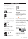
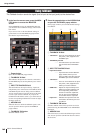
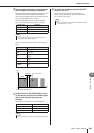
5
Press the [CUE] key of a desired channel or
DCA group to turn it on.
The Cue signal of the corresponding channel will be
sent to the monitor signal output destination.
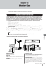
The background of the Cue meter in the function
access area will turn blue, indicating the Cue output
level. An abbreviation of the currently-on Cue group
or button is shown above the Cue meter.
The abbreviations displayed for the Cue meter have
the following meaning.
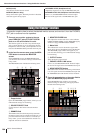
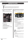
6
To adjust the Cue signal level, use the
MONITOR LEVEL knob located in the
SCENE MEMORY/MONITOR section of the
top panel.
If PHONES LEVEL LINK is ON, you can use both
the MONITOR LEVEL knob and the PHONES
LEVEL knob to adjust the Cue signal level when mon-
itoring through headphones.
• [CUE] keys belonging to different Cue groups cannot be
turned on simultaneously. The Cue group to which the last-
pressed [CUE] key belongs will be turned on, allowing only
the signals of that group to be monitored.
HINT
IN INPUT CUE group
DCA DCA CUE group
OUT OUTPUT CUE group
EFFECT
CUE button in the EFFECT popup window
(Other cue group)
KEY IN
KEY IN CUE button of the DYNAMICS 1 popup
window (Other cue group)
CUE meter
• When using the MIX or MATRIX bus select buttons in the
SENDS ON FADER popup window, you can press the
selected button once again to turn on Cue for the correspond-
ing MIX or MATRIX channel (
→
p. 70).
• If you want Cue operations and channel select operations to
be linked, open the USER SETUP popup window, choose the
PREFERENCE tab, and turn “[CUE]>[SEL] LINK” on (
→
p. 214
).
HINT