


M7CL Owner’s Manual
Using EQ
116
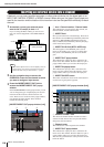
C
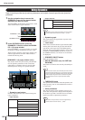
FLAT button
This button resets the GAIN parameters of all bands to
the default value (0.0 dB). If you press this button, a
confirmation dialog box will appear.
D
HIGH shelving button
If this button is on, the HIGH band EQ will function as
a shelving-type EQ. In this case, the HIGH band Q
knob is not shown.
E
Low pass filter button
If this button is on, the HIGH band EQ will function as
a low-pass filter. In this case, the HIGH band Q knob
is not shown, and the GAIN knob will act as an on/off
switch for the low pass filter.
F
EQ ON/OFF button
Switches the EQ on/off.
G
Level meter
These meters indicate the peak levels before EQ and
after EQ. If the signal clips before or after EQ, the
OVER segment will light. If the corresponding chan-
nel is stereo (a ST IN channel, a MIX/MATRIX chan-
nel set to stereo, or the STEREO channel), level
meters for two channels are displayed.
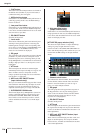
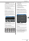
H
EQ graph
This graph shows the approximate response of the EQ
parameters. A pointer is shown at the peak of each
band. The response curve will change when you edit
the Q, FREQUENCY, or GAIN knobs of each band. If
the EQ or high-pass filter is on, the response curve is
highlighted.
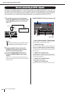
I
ATT knob
This knob adjusts the amount of attenuation/gain
immediately before input to the EQ, in a range of -96
dB to +24 dB. Use this to compensate for level
changes produced by the EQ. You can use multifunc-
tion encoder 1 to control this.
J
HPF knob, HPF ON/OFF button
(input channels only)
Here you can switch on/off the high pass filter located
after attenuation and before EQ, and adjust its cutoff
frequency. You can use multifunction encoder 2 to
adjust the cutoff frequency in a range of 20–600 Hz.
K
Q/FREQUENCY/GAIN knobs
These knobs adjust the Q, FREQUENCY (center fre-
quency), and GAIN (amount of boost/cut) for each
band (LOW, LOW MID, HIGH MID, and HIGH).
Press a knob to select the band you want to control,
and use multifunction encoders 3–8 to make adjust-
ments.
L
High-pass filter button
(output channels only)
If this button is on, the LOW band EQ will function as
a high-pass filter. In this case, the LOW band Q knob
is not shown, and the GAIN knob will act as an on/off
switch for the high-pass filter.
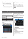
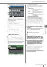
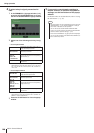
[ATT/HPF/EQ popup window (8 ch)]
This shows the input channel or output channel EQ
settings in groups of eight channels at a time.
Use the encoders of the SELECTED CHANNEL sec-
tion to edit the EQ settings. This window lets you con-
trol the ATT and HPF settings of all eight channels
shown.
1
Channel select button
This indicates the channel number, the icon selected
for that channel, and the channel name. Press these
buttons to select the channel you want to copy or
paste, or to select multiple channels.
B
EQ graph
This mini-graph shows the approximate response of
the EQ parameters. You can press the EQ graph to
switch to the one-channel window with that channel
selected. If the EQ or high-pass filter is on, the
response curve is highlighted.
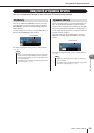
C
EQ ON/OFF button
Switches the EQ on/off.
D
ATT knob
This knob adjusts the attenuation / gain amount before
the signal enters the EQ. You can press the ATT knob
to select it, and then use multifunction encoders 1–8 to
make adjustments.
E
HPF knob, HPF ON/OFF button (input
channels only)
These controls switch the high-pass filter on/off, and
adjust its cutoff frequency. You can press the HPF
knob to select it, and then use multifunction encoders
1–8 to make adjustments.
L
1
2
3
4
5