


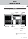
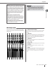
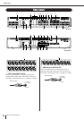
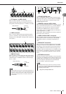

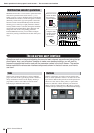

Rear panel
Panels and controls
25
M7CL Owner’s Manual
2
C
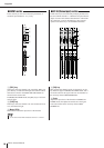
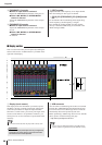
ST IN jacks 1–4 (M7CL-38/48)
These are balanced XLR-3-31 female input jacks for
inputting analog audio signals from line level devices or
microphones. Nominal input level is -62 dBu to +10 dBu.
D
LAMP connector
This is a four-pin female XLR output jack that supplies
power to a separately sold gooseneck lamp (such as the
Yamaha LA1L). (The M7CL-32 features this connector at
one location.)
E
OMNI OUT jacks
These are XLR-3-32 male output jacks that output analog
audio signals. These are used mainly to output the signals
of MIX channels or MATRIX channels. Nominal output
level is +4 dBu.
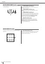
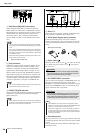
F
2TR OUT DIGITAL jack
This is an AES/EBU (XLR-3-32 male) jack that outputs
the digital audio signal of a desired channel in AES/EBU
format. This is used mainly to output the signal of the
STEREO/MONO channel.
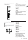
G
REMOTE connector (M7CL-32/48)
This is a D-sub 9-pin male connector for remotely control-
ling an external head amp device (e.g., Yamaha AD8HR)
that supports a special protocol. It can also be used to
transmit/receive MIDI messages to/from an external
device. Refer to the pin assignment table for information
on pin assignments. (
→
p. 298)
On the M7CL-48ES, the EtherSound connector duplicates
the function of this connector.
H
WORD CLOCK IN/OUT connectors
These are BNC connectors used to transmit/receive word
clock signals to/from an external device. The WORD
CLOCK IN connector is internally terminated by 75
ohms.
I
MIDI IN/OUT connectors
These connectors are used to transmit and receive MIDI
messages to and from external MIDI devices. The MIDI
IN connector receives messages from an external device,
and the MIDI OUT connector transmits messages from
the M7CL. These are used mainly to record M7CL param-
eter operations or scene/library selections on an external
device, or to control M7CL parameters from an external
device.
J
NETWORK connector
This RJ-45 connector allows the M7CL to be connected to
a computer via an Ethernet cable (CAT5e or higher recom-
mended). This is used mainly to control mix parameters or
edit scene memories and libraries from the dedicated
“M7CL V3 Editor” application program.
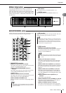
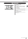
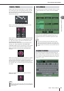
C
D
2 (hot)
3 (cold)
1 (ground)
Male XLR plug
E
1 (ground)
3 (cold)
2 (hot)
Female XLR plug
• Although OMNI OUT jacks have a nominal input/output level of +4
dBu (maximum level +24 dBu), an internal switch allows this to be
changed to -2 dBu (maximum level +18 dBu) if necessary. (A fee
will be charged for this procedure.) For details, contact to your
Yamaha dealer.
NOTE
FGJ 9H
• The DME-N Network Driver required for connection to the Ether-
net connector, the Studio Manager required for starting up M7CL
V3 Editor, and the M7CL V3 Editor itself can be downloaded from
the following Yamaha website.
http://www.yamahaproaudio.com/
NOTE