


M7CL Owner’s Manual
Effects Parameters
256
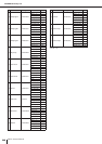
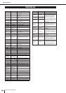
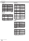
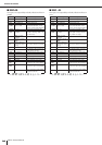
■ TREMOLO
Two input, two output tremolo effect.
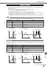
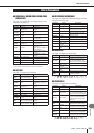
■ HQ. PITCH
One input, two output high-quality pitch shifter.
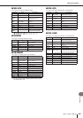
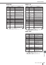
■ DUAL PITCH
Two input, two output pitch shifter.
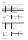
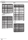
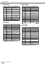
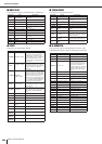
■ ROTARY
One input, two output rotary speaker simulator.
■ RING MOD.
Two input, two output ring modulator.
Parameter Range Description
FREQ. 0.05–40.00 Hz Modulation speed
DEPTH 0–100% Modulation depth
WAVE Sine, Tri, Square Modulation waveform
SYNC OFF/ON Tempo parameter sync on/off
NOTE
*1
*1.
Used in conjunction with TEMPO
to determine FREQ.
LSH F 21.2 Hz–8.00 kHz Low shelving filter frequency
LSH G –12.0 to +12.0 dB Low shelving filter gain
EQ F 100 Hz–8.00 kHz EQ (peaking type) frequency
EQ G –12.0 to +12.0 dB EQ (peaking type) gain
EQ Q 10.0–0.10 EQ (peaking type) bandwidth
HSH F 50.0 Hz–16.0 kHz High shelving filter frequency
HSH G –12.0 to +12.0 dB High shelving filter gain
Parameter Range Description
PITCH –12 to +12 semitones Pitch shift
FINE –50 to +50 cents Pitch shift fine
DELAY 0.0–1000.0 ms Delay time
FB. GAIN –99 to +99%
Feedback gain (plus values for
normal-phase feedback, minus
values for reverse-phase feed-
back)
MODE 1–10 Pitch shift precision
SYNC OFF/ON Tempo parameter sync on/off
NOTE
*1
*1.
(Maximum value depends on the tempo setting)
Used in conjunction with
TEMPO to determine DELAY
Parameter Range Description
PITCH 1 –24 to +24 semitones Channel #1 pitch shift
FINE 1 –50 to +50 cents Channel #1 pitch shift fine
LEVEL 1 –100 to +100%
Channel #1 level (plus values
for normal phase, minus values
for reverse phase)
PAN 1 L63 to R63 Channel #1 pan
DELAY 1 0.0–1000.0 ms Channel #1 delay time
FB. G 1 –99 to +99%
Channel #1 feedback gain (plus
values for normal-phase feed-
back, minus values for
reverse-phase feedback)
MODE 1–10 Pitch shift precision
PITCH 2 –24 to +24 semitones Channel #2 pitch shift
FINE 2 –50 to +50 cents Channel #2 pitch shift fine
LEVEL 2 –100 to +100%
Channel #2 level (plus values
for normal phase, minus values
for reverse phase)
PAN 2 L63 to R63 Channel #2 pan
DELAY 2 0.0–1000.0 ms Channel #2 delay time
FB. G 2 –99 to +99%
Channel #2 feedback gain (plus
values for normal-phase feed-
back, minus values for
reverse-phase feedback)
SYNC OFF/ON Tempo parameter sync on/off
NOTE 1
*1
*1.
(Maximum value depends on the tempo setting)
Used in conjunction with
TEMPO to determine Channel
#1 delay
NOTE 2
*1
Used in conjunction with
TEMPO to determine Channel
#2 delay
Parameter Range Description
ROTATE STOP, START Rotation stop, start
SPEED SLOW, FAST
Rotation speed (see SLOW and
FAST parameters)
SLOW 0.05–10.00 Hz SLOW rotation speed
FAST 0.05–10.00 Hz FAST rotation speed
DRIVE 0–100 Overdrive level
ACCEL 0–10 Acceleration at speed changes
LOW 0–100 Low-frequency filter
HIGH 0–100 High-frequency filter
Parameter Range Description
SOURCE OSC, SELF
Modulation source: oscillator or
input signal
OSC FREQ 0.0–5000.0 Hz Oscillator frequency
FM FREQ. 0.05–40.00 Hz
Oscillator frequency modulation
speed
FM DEPTH 0–100%
Oscillator frequency modulation
depth
SYNC OFF/ON Tempo parameter sync on/off
FM NOTE
*1
*1.
Used in conjunction with TEMPO
to determine FM FREQ