


M7CL Owner’s Manual
108
5
Use the channel select tabs and the chan-
nel select buttons to select the source
channel, and press the CLOSE button.
You will return to the OUTPUT PORT popup window.
6
Make settings for delay, phase, and attenu-
ator as desired.
7
Repeat step 3–6 to assign channels for
other output ports.
8
When you have finished making settings,
click the “×” symbol in the upper right of
the window to return to the previous
screen.
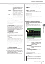
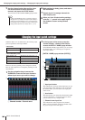
When the M7CL is in its default state, the following input
ports are patched to each input channel.
• M7CL-32/48
• M7CL-48ES (Daisy chain)
However, the above patching can be changed as desired.
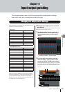
Here we will explain how to change the patching for each
input channel.
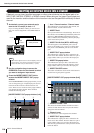
1
Use the navigation keys to access the
OVERVIEW screen for the input channels
whose input source you want to change.
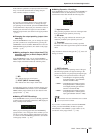
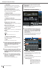
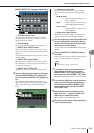
1 Channel number / Channel name
2
In the top part of the screen, press the
channel number / channel name field to
access the PATCH / NAME popup window.
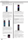
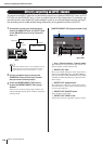
In the PATCH / NAME popup window you can change
the channel name, icon, and input port assigned to
each input channel.
[PATCH / NAME popup window (PATCH)]
1 Input port button
This indicates the currently selected input port. If you
press this button when selecting an icon or changing
the channel name, you will return to the input port
select screen.
B Icon button
This indicates the icon selected for that channel. When
you press this button, a screen will appear in which
you can select an icon or sample name.
C Channel name input box
This indicates the name assigned to that channel.
When you press this field, a keyboard window allow-
ing you to assign a name will appear.
• If PATCH CONFIRMATION is ON, a confirmation dialog box
will appear when you attempt to change the patch settings. If
STEAL PATCH CONFIRMATION is ON, a confirmation dialog
box will appear when you attempt to change a location that is
already patched elsewhere. (For details, refer to
→ p. 214).
HINT
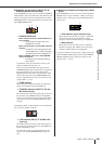
Changing the input patch settings
INPUT channels 1–32 {1–48} INPUT jacks 1–32 {1–48}
ST IN channels 1–4 RACK 5–8
INPUT channels 1–16 SB168-ES (ID #1) INPUT jacks 1–16
INPUT channels 17–32 SB168-ES (ID #2) INPUT jacks 1–16
INPUT channels 33–48 SB168-ES (ID #3) INPUT jacks 1–16
ST IN channels 1–4 RACK 5–8
1
1
4
5
6
2 3
Changing the output patch settings • Changing the input patch settings