


M7CL Owner’s Manual
46
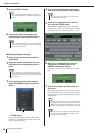
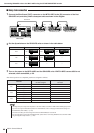
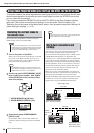
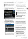
After the steps above are completed, patches are assigned as follows:
*1: Since the total number of input and output channels is limited to 64 in ring networks, an identical audio signal will be output to SB168-ES units ID#2
and ID#3.
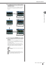
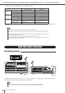
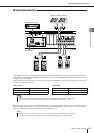
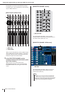
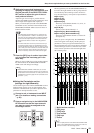
The INPUT and OMNI IN jacks are used mainly to connect microphones or monaural line-level devices. The ST IN jacks
are used mainly to connect microphones or stereo line-level devices.
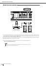
SB168-ES
EtherSound patches set via
the Auto Configure
M7CL-48ES patches set via
scene 000
ID #1
INPUT 1–16 jacks ES IN 1–16 CH 1–16
OUTPUT 1–6 jacks ES OUT 1–6 MIX 1–6
OUTPUT 7/8 jacks ES OUT 7/8 STEREO L/R
ID #2
INPUT 1–16 jacks ES IN 17–32 CH 17–32
OUTPUT 1–6 jacks ES OUT 9–14 MIX 7–12
OUTPUT 7/8 jacks ES OUT 15/16 STEREO L/R
ID #3
INPUT 1–16 jacks ES IN 33–48 CH 33–48
OUTPUT 1–6 jacks ES OUT 9–14
*1
MIX 7–12
*1
OUTPUT 7/8 jacks ES OUT 15/16
*1
STEREO L/R
*1
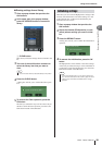
• If you select a ring connection, word clock master will be set to EtherSound (48kHz).
•To change the input or output channel patches on the M7CL-48ES, access the M7CL-48ES PATCH/NAME popup win-
dow.
• If you want to change the EtherSound patches from AVS-ESMonitor, refer to “Changing the EtherSound settings from
AVS-ESMonitor (M7CL-48ES)” (
→
p. 243).
• The word clock setting cannot be changed if the AUTO CONFIGURE button is turned ON.
•For more information on the AUTO CONFIGURE button, please refer to “Connecting SB168-ES units to the M7CL-48ES
using the Stage Box Setup function” (
→
p. 242).
NOTE
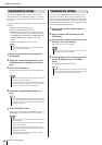
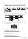
Audio input/output connections
■ Analog input connections
M7CL-48
SB168-ES
• In the default state, the ST IN or OMNI IN jacks are not patched. (Racks 5–8 are assigned to the ST IN
channels.) In order to use the signals connected here as inputs, you will need to make patch settings.
NOTE
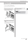
Connecting SB168-ES units to the M7CL-48ES using the STAGE BOX SETUP function • Audio input/output connections