


Viewing the touch screen
33
M7CL Owner’s Manual
Basic operation of the M7CL
3
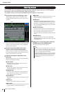
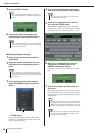
If the oscillator or talkback is enabled, this area will indi-
cate “OSC” or “TB” respectively. If cue monitor is on, the
type of signal being cue-monitored (IN/OUT/DCA/KEY
IN/EFFECT) is shown. An indication of “ACCESS” is
shown while a USB storage device attached to the USB
connector is being accessed.
D
Help
This button is used to show on-line help in the main area.
To view the on-line help, first you must load the help file
from the USB storage device (
→
p. 225).
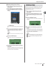
E
SENDS ON FADER
Press this button to switch to SENDS ON FADER mode,
where you can use the faders of the top panel to adjust the
MIX/MATRIX send level (
→
p. 70). During this time, the
function access area of the touch screen will change to a
screen allowing you to select the send-destination MIX/
MATRIX bus.
F
CH JOB (Channel Job)
Press this button to switch to CH JOB mode, where you
can make settings for channel grouping and linking (
→
p. 123). During this time, the function access area of the
touch screen will change to a screen allowing you to select
the function you want to operate.
G
RACK
When you press this button, the VIRTUAL RACK screen
will appear in the main area, allowing you to edit the GEQ
or effect settings (
→
p. 172).
H
MONITOR
When you press this button, the MONITOR screen will
appear in the main area, allowing you to edit the monitor
or oscillator settings (
→
p. 154
).
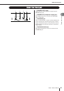
I
METERS
These are level meters that monitor the level of the STE-
REO bus (L/R), MONO bus (M), and cue signal (CUE).
When you press this field, the METER screen will appear
in the main area, displaying the meters and fader status for
all channels at once (
→
p. 167). If you press this field
when the cue monitor is on, the cue monitor will be can-
celed (equivalent to CUE CLEAR).
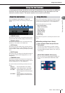
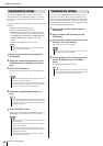
J
SETUP
When you press this button, the SYSTEM screen will
appear in the main area, allowing you to make basic sys-
tem settings and user-specific settings (
→
p. 229).
K
SCENE
This indicates the number and name of the scene that was
last stored or recalled. An “R” symbol is displayed for
read-only scenes, and a lock icon is displayed for write-
protected scenes. If you edit the parameters from their last
stored or recalled state, an “ ” symbol will appear in
the lower right.
When you press this field, the SCENE LIST screen will
appear in the main area, allowing you to store or recall
scenes (
→
p. 135).
When you press a button
7
through
K
to access the cor-
responding screen, the button will be highlighted. In this
state, pressing the button once again will return either to
the most recently recalled SELECTED CHANNEL VIEW
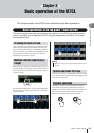
screen or the OVERVIEW screen.
The contents of the main area will change depending on
the function that is currently selected. Mixing operations
will involve mainly the following two types of screen.
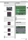
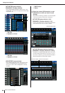
■
SELECTED CHANNEL VIEW screen
This screen shows all the mix parameters for the currently
selected channel. To access this screen, click one of the
encoders of the SELECTED CHANNEL section.
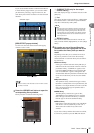
■
OVERVIEW screen
This screen simultaneously shows the main parameters for
the (up to) eight channels currently assigned to the Centr-
alogic section. To access this screen, press one of the keys
in the NAVIGATION KEYS section or one of the multi-
function encoders.
• Do not disconnect the USB connector while the “ACCESS” indica-
tion is shown here. Doing so may damage the data on the USB
storage device.
NOTE
Main area
• While the HELP, METER or SCENE screen is displayed in the
main area, the OVERVIEW screen will not open even if you press
a key in the NAVIGATION KEYS section. To return to the OVER-
VIEW screen, press a user-defined key to which the OVERVIEW
function is assigned. Alternatively, press the HELP, METER or
SCENE field once again.
HINT