


Installing Optional Hardware
186
Owner’s Manual
Appendix
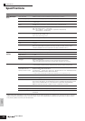
6 Connect the cable to the Plug-in Board.
Make sure to connect the proper cable, matching the color
of the cable to the slot used.
7 Carefully put the cable back into the S90 ES, making
sure that no part of the cable sticks out of the
instrument.
8 Replace the cover with the screw you removed in
step 2 above.
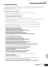
9 Check that the installed Plug-in board is functioning
properly.
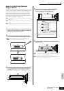
After connecting the AC power cord to the S90 ES, turn on
the power. The main display then appears and the
corresponding slot indicator at the right top of the front
panel lights. This indicates that the board has been
successfully installed. If the cable is not connected
properly or firmly, the indicator will not light.
Installing the mLAN16E
The mLAN expansion board (mLAN16E) sold separately
can be installed to this instrument.
1 Turn the S90 ES’s power off, and disconnect the AC
power cord. Also, make sure to disconnect the S90
ES from any other external devices.
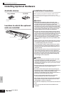
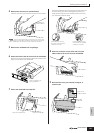
2 Turn over the S90 ES so you can have direct access
to the underside.
To protect the wheels and sliders, place the keyboard so
the four corners are supported by something that provides
sufficiently high and firm support, such as magazines or
cushions.
Since this instrument is very heavy, this procedure should not be done
alone, but by two or three people.
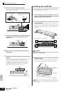
3 Remove the top cover on the rear of the instrument
(as shown below).
With the rear panel facing you, remove the screws of the
top cover, then remove the cover from the instrument.
Keep the removed screws in a safe place. They will be used
when attaching the cover to the S90 ES again after installing the mLAN16E.
Also make sure to keep the cover in a safe place. Do not leave the cover
inside the instrument.
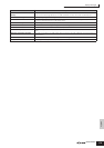
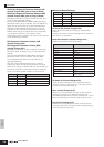
Plug-in SLOT
GREEN
YELLOW
ORANGE
3
2
1
Plug-in connector
Notch
Connector from S90 ES Plug-in board
Press the connectors together
until the two notches lock into
the sockets.
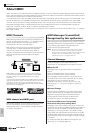
Plug-in SLOT
GREEN
YELLOW
ORANGE
3
2
1
PRE 4
GUITAR/
PLUCKED
STRINGS
PLG 1
SLOT
1
SLOT 2
SLOT 3
BRASS
PLG 2
REED/PIPE
PLG 3
BASS
GM
CATEGORY
SEARCH
Slot indicator
In this example, a Plug-in board has been installed to slot 1.
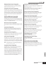
View of the keyboard from the bottom
Place supports at all four corners, taking
care not to touch the wheels and sliders.
CAUTION