


ix Table of Contents
Models SE and DL
Logging (optional) ................................................................................................ 133
Part numbers ........................................................................................................ 133
Replacement parts ........................................................................................................ 133
Optional parts ................................................................................................................ 134
Port pinouts .......................................................................................................... 135
AC/DC jack.......................................................................................................................... 135
Auxiliary connector .............................................................................................................. 135
Block Diagram for SoundPro .............................................................................. 136
Glossary of Terms ................................................................................................ 137
Customer service ................................................................................................. 149
Contacting 3M ...................................................................................................... 149
Warranty ............................................................................................................... 150
FIGURES
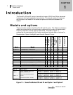
Figure 1-1: SoundPro Models SE and DL and Option 1 and Option 2........................................... 1
Figure 1-2: Octave bands .................................................................................................................. 2
Figure 1-3: Third Octave bands ........................................................................................................ 3
Figure 1-4: Hardware Interface Panel ............................................................................................... 6
Figure 1-5: The Unit Information screen .......................................................................................... 8
Figure 2-1: Identify SoundPro equipment ...................................................................................... 11
Figure 2-2: SoundPro & Preamp ..................................................................................................... 12
Figure 2-3: SoundPro with microphone and windscreen ............................................................. 13
Figure 2-4: Installing batteries ........................................................................................................ 14
Figure 2-5: Battery check screen ................................................................................................... 15
Figure 2-6: Selecting Setup in the Start Screen ............................................................................ 16
Figure 2-7: Selecting battery type in battery check screen .......................................................... 16
Figure 2-8: Attaching the charger adapter with the plug adapter ................................................ 17
Figure 2-9: Base (or bottom) of SoundPro .................................................................................... 17
Figure 2-10: SoundPro SE/DL start screen and keypad ................................................................. 18
Figure 3-1: Microphone Settings (Signal Input screen) ................................................................ 24
Figure 3-2: Time and Date Settings ................................................................................................ 25
Figure 3-3: Measurement type and start screen ........................................................................... 26
Figure 3-4: Meter 1 and Meter 2 parameters .................................................................................. 27
Figure 3-5: Measures screen for community noise settings ........................................................ 28
Figure 3-6: C-A measurement settings for Meter 1 and Meter 2 .................................................. 30
Figure 3-7: Logged Data Chart example ........................................................................................ 31
Figure 3-8: Logging screen explained ........................................................................................... 32
Figure 3-9: Display setup screen .................................................................................................... 33
Figure 3-10: Language screen .......................................................................................................... 34
Figure 3-11: Backlight setting ........................................................................................................... 35
Figure 4-1: Auto-Run with Date selected ....................................................................................... 38