


7 - 3
7.2 For Use in Normal System Configuration
7
PROGRAMMING
7.2 For Use in Normal System Configuration
This section describes a program example under the following system configuration and
use conditions.
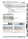
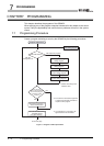
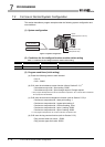
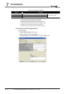
(1) System configuration
Figure 7.2 System configuration
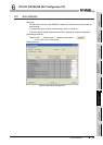
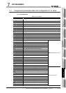
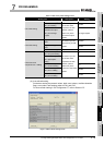
(2) Conditions for the intelligent function module switch setting
Table 7.1 Conditions for the intelligent function module switch setting
(3) Program conditions (intial setting)
(a) Preset the following values to each channel.
• CH1: 0
• CH2: - 50000
(b) CH1 uses the coincidence output function (refer to Section 5.3.1).
*1
• Coincidence output No.1 point setting: 10000
• Coincidence output No.1 point change request: Change request
* 1:This program example does not use the coincidence output No.2. CH1 counter value coincidence
No.2 (X05) turns ON at default.
(c) CH2 uses the continuous comparison function (refer to Section 5.3.2).
*2
• Continuous comparison No.1 start point setting: 1
• Continuous comparison No.1 repeat point setting: 2
• Continuous comparison No.1 ON time setting: 10ms
• Continuous comparison No.1 point 1 setting: 20000
• Continuous comparison No.1 point 2 setting: 40000
* 2: This program example does not use the continuous comparison No.2.
(d) CH2 uses the ring counter function (refer to Section 5.2.2).
• Ring counter lower limit value: - 50000
• Ring counter upper limit value: 50000
Channel Pulse input mode Counter format Counter value comparison function selection
CH1 CW/CCW Linear counter Coincidence output function
CH2 CW/CCW Ring counter Continuous comparison function
CH1 encoder
CH2 encoder
QY40P(Y30 to Y3F)
QX40(X20 to X2F)
QCPU
QD64D2(X/Y00 to X/Y1F)