


5
FUNCTIONS
5.3 Using the Counter Value Comparison Function
5.3.4 Coincidence detection interrupt function
5 - 25
1
OVERVIEW
2
SYSTEM
CONFIGURATION
3
SPECIFICATIONS
4
PROCEDURES AND
SETTINGS BEFORE
OPERATION
5
FUNCTIONS
6
UTILITY PACKAGE (GX
Configurator-CT)
7
PROGRAMMING
8
TROUBLESHOOTING
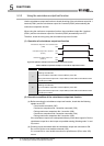
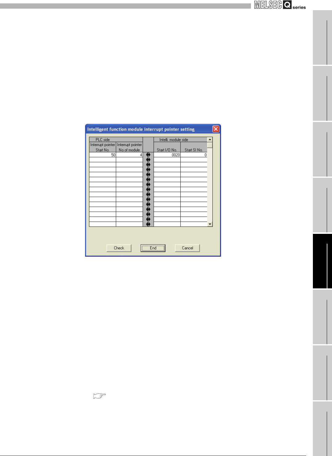
2) [PLC side] [Interrupt pointer No. of module]
Set the number of interrupt factors (SI).
Setting range: 1 to 4
3) [Intelli. module side] [Start I/O No.]
Set the start I/O number of the QD64D2.
Setting range: 0000 to 0FE0(
H)
4) [Intelli. module side] [Start SI No.]
Set the start interrupt factor (SI) of the QD64D2.
Setting range: 0 to 3
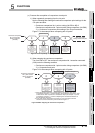
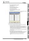
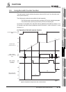
The following shows a setting example where SI 0 to 3 of the QD64D2 in the slot
of start I/O No.20 are assigned to interrupt pointers I50 to I53.
Figure 5.11 Interrupt pointer setting example (GX Developer screen)
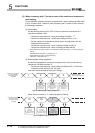
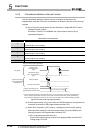
(d) The following two methods are available for using particular SI numbers only.
1) Using the interrupt pointer setting with parameters
According to the setting in the [Intelligent function module interrupt pointer
setting] dialog box, only the interrupt factors starting from the [Start SI No.] and
equivalent to the number set at [Interrupt pointer No. of module] are used.
For example, if the [Start SI No.] and [Interrupt pointer No. of module] are set to
1 and 2 respectively, only SI 1 and 2 will be used.
The interrupt function is not used if the interrupt pointer setting with parameters
has not been made.
2) Using the IMASK instruction from the sequence program
With the IMASK instruction, whether to enable or disable (interrupt mask) the
interrupt program execution can be set to each interrupt pointer number.
For details of the IMASK instruction, refer to the following manual.
MELSEC-Q/L Programming Manual (Common Instruction)