


3
SPECIFICATIONS
3.4 Buffer Memory Assignment
3.4.2 Details of the buffer memory
3 - 19
1
OVERVIEW
2
SYSTEM
CONFIGURATION
3
SPECIFICATIONS
4
PROCEDURES AND
SETTINGS BEFORE
OPERATION
5
FUNCTIONS
6
UTILITY PACKAGE (GX
Configurator-CT)
7
PROGRAMMING
8
TROUBLESHOOTING
3.4.2 Details of the buffer memory
This section describes details of the QD64D2 buffer memory.
In this section, I/O numbers (X/Y) and buffer memory addresses are listed for channel 1
and coincidence output No.1. For I/O numbers and buffer memory addresses used for
channel 2 and coincidence output No.2, refer to Section 3.3.1 and Section 3.4.1.
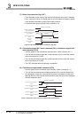
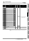
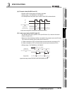
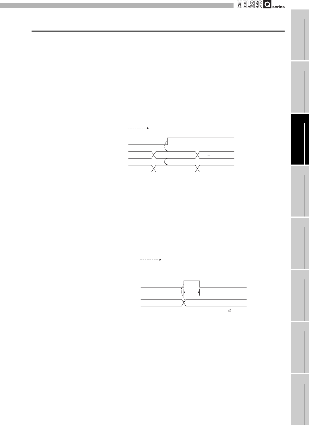
(1) Ring counter lower limit value (Un\G0 and 1)
Ring counter upper limit value (Un\G2 and 3)
• This area is used for setting a count range for the ring counter. (Refer to Section
5.2.2.)
• Setting range: -2147483648 to 2147483647
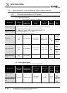
Figure 3.18 Timing chart for the ring counter lower limit value (Un\G0 and 1) and ring counter upper limit value (Un\G2 and 3)
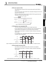
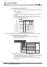
(2) Preset value setting (Un\G4 and 5)
• This area is used for setting a preset value for the counter. (Refer to Section 5.4.)
• Setting range: -2147483648 to 2147483647
• The setting value becomes effective when the preset command (Y04) or the
preset input terminal (PRST) is turned from OFF to ON.
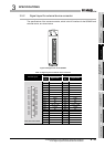
Figure 3.19 Timing chart for the preset value setting (Un\G4 and 5)
ON
200 1000
2001000
*1
*1
*2
*2
Operation by the QD64D2
Count enable command
(Y06)
Ring counter lower limit value
(Un\G0 and 1)
Ring counter upper limit value
(Un\G2 and 3)
*1 Setting value of the ring counter upper limit value (Un\G2 and 3) and the ring counter lower
limit value (Un\G0 and 1) becomes effective when the count enable command (Y06) is turned
from OFF to ON.
*2 It does not become effective until the count enable command (Y06) is turned from OFF to ON.
OFF
ON
* t 2ms
t*
100
1000
Operation by the QD64D2
Preset value setting
(Un\G4 and 5)
Preset command
(Y04)
Present value
(Un\G12 and 13)