


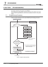
7
PROGRAMMING
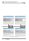
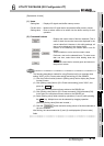
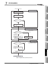
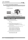
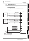
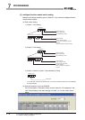
7.3 Programming Example when GX Configurator-CT is Used
7 - 6
1
OVERVIEW
2
SYSTEM
CONFIGURATION
3
SPECIFICATIONS
4
PROCEDURES AND
SETTINGS BEFORE
OPERATION
5
FUNCTIONS
6
UTILITY PACKAGE (GX
Configurator-CT)
7
PROGRAMMING
8
TROUBLESHOOTING
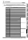
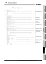
7.3 Programming Example when GX Configurator-CT is Used
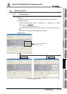
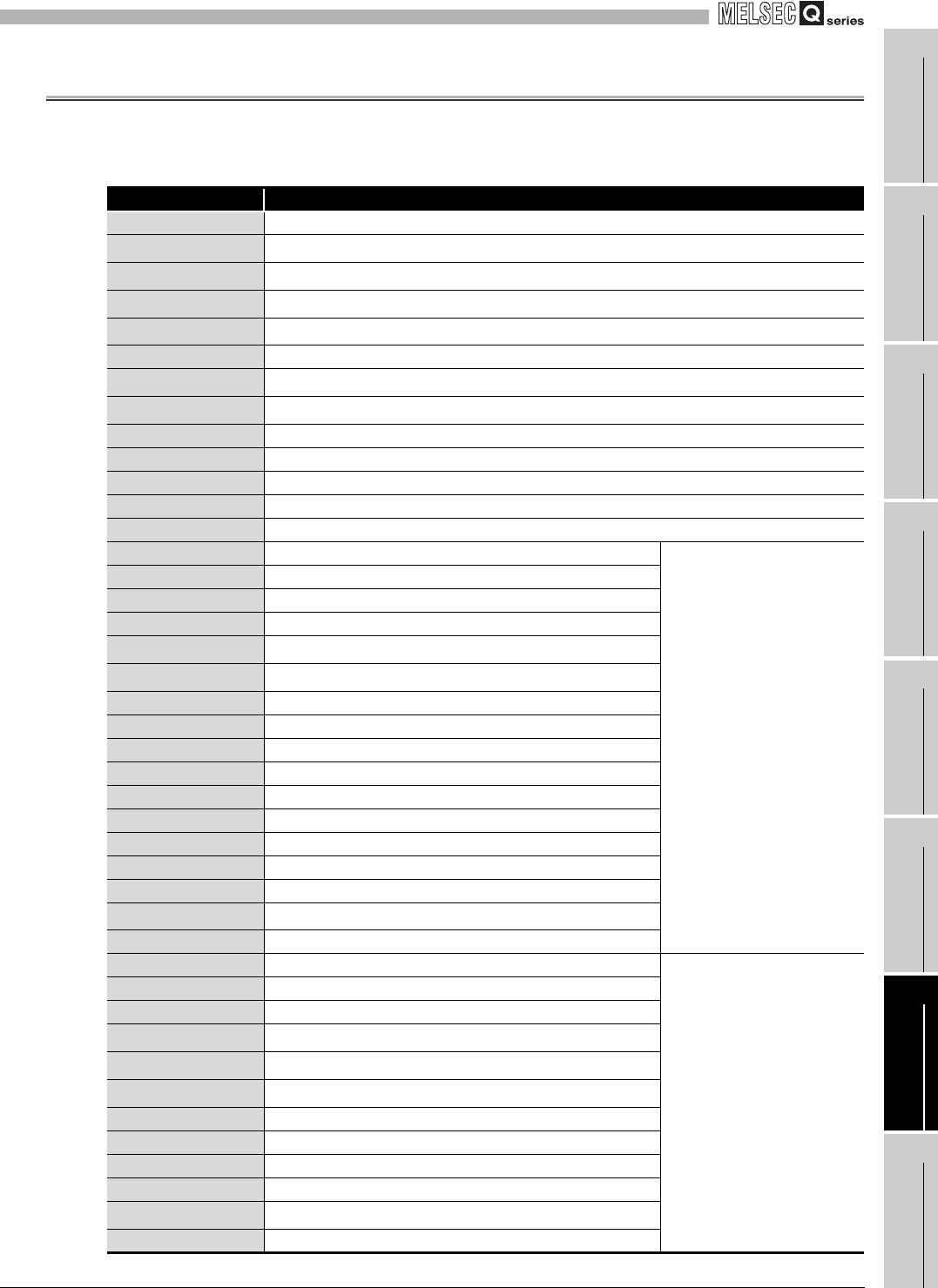
(1) List of devices
Table 7.2 List of devices
Device Function
D0,D1 CH1 present value storage
D2,D3
*1
CH1 latch count value storage
D4
*2
CH1 overflow status storage
D5
*3
CH1 error code storage
D6
*4
CH1 warning code storage
D8,D9 CH2 present value storage
D10
*3
CH2 error code storage
D11
*4
CH2 warning code storage
D118 CH1 error code
D119 CH1 warning code
D120 CH2 error code
D121 CH2 warning code
M10 Initial setting complete signal
X00 Module READY
QD64D2 (X/Y00 to X/Y1F)
X02 CH1 counter value coincidence No.1
X0D CH1 error occurrence
X0E CH1 warning occurrence
Y01
*5
CH1 coincidence signal No.1 reset command
Y03
*5
CH1 coincidence output enable command
Y04 CH1 preset command
Y06 CH1 count enable command
Y07 CH1 latch counter execution command
Y0D CH1 error reset command
X12 CH2 counter value coincidence No.1
X1D CH2 error occurrence
X1E CH2 warning occurrence
Y14 CH2 preset command
Y16 CH2 count enable command
Y19
*6
CH2 continuous comparison No.1 execution command
Y1D CH2 error reset command
X20 CH1 count operation start signal
QX40 (X20 to X2F)
X21 CH1 count operation stop signal
X23 CH1 preset command signal
X24
*1
CH1 latch execution command signal
X26
*5
CH1 coincidence output enable signal
X27
*5
CH1 coincidence LED clear signal
X28 CH1 error/warning reset command signal
X2A CH2 count operation start signal
X2B CH2 count operation stop signal
X2D CH2 preset command signal
X2E
*6
CH2 continuous comparison execution signal
X2F CH2 error/warning reset command signal