


3
SPECIFICATIONS
3.5 Specifications of I/O Interfaces with External Device
3.5.2 Signal layout for external device connector
3 - 25
1
OVERVIEW
2
SYSTEM
CONFIGURATION
3
SPECIFICATIONS
4
PROCEDURES AND
SETTINGS BEFORE
OPERATION
5
FUNCTIONS
6
UTILITY PACKAGE (GX
Configurator-CT)
7
PROGRAMMING
8
TROUBLESHOOTING
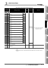
3.5.2 Signal layout for external device connector
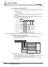
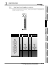
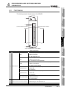
The specifications of the connector section, which is the I/O interface for the QD64D2 and
external device, are shown below.
Figure 3.25 Appearance of the QD64D2
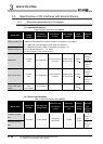
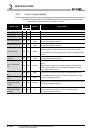
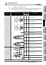
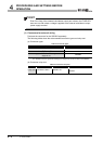
Table 3.8 Signal layout for external device connector
Terminal layout
CH1 CH2
Terminal
number
Signal name
Terminal
No.
Signal name
Front view of the module
B20 NC A20 NC
B19 PULSE A + A19 PULSE A +
B18 PULSE A - A18 PULSE A -
B17 PULSE B + A17 PULSE B +
B16 PULSE B - A16 PULSE B -
B15 PULSE COM A15 PULSE COM
B14 NC A14 NC
B13 PRST COM A13 PRST COM
B12 PRST A12 PRST
B11 NC A11 NC
B10 NC A10 NC
B09 LATCH COM A09 LATCH COM
B08 LATCH A08 LATCH
B07 NC A07 NC
B06 NC A06 NC
B05 EQU1 A05 EQU1
B04 EQU2 A04 EQU2
B03 12V/24V A03 12V/24V
B02 0V A02 0V
B01 NC A01 NC
B20
B19
B18
B17
B16
B15
B14
B13
B12
B11
B10
B09
B08
B07
B06
B05
B04
B03
B02
B01
A20
A19
A18
A17
A16
A15
A14
A13
A12
A11
A10
A09
A08
A07
A06
A05
A04
A03
A02
A01