


3 - 24
3.5 Specifications of I/O Interfaces with External Device
3.5.1 Electrical specifications of I/O signals
3
SPECIFICATIONS
3.5 Specifications of I/O Interfaces with External Device
3.5.1 Electrical specifications of I/O signals
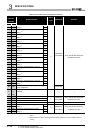
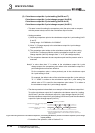
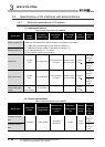
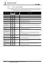
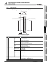
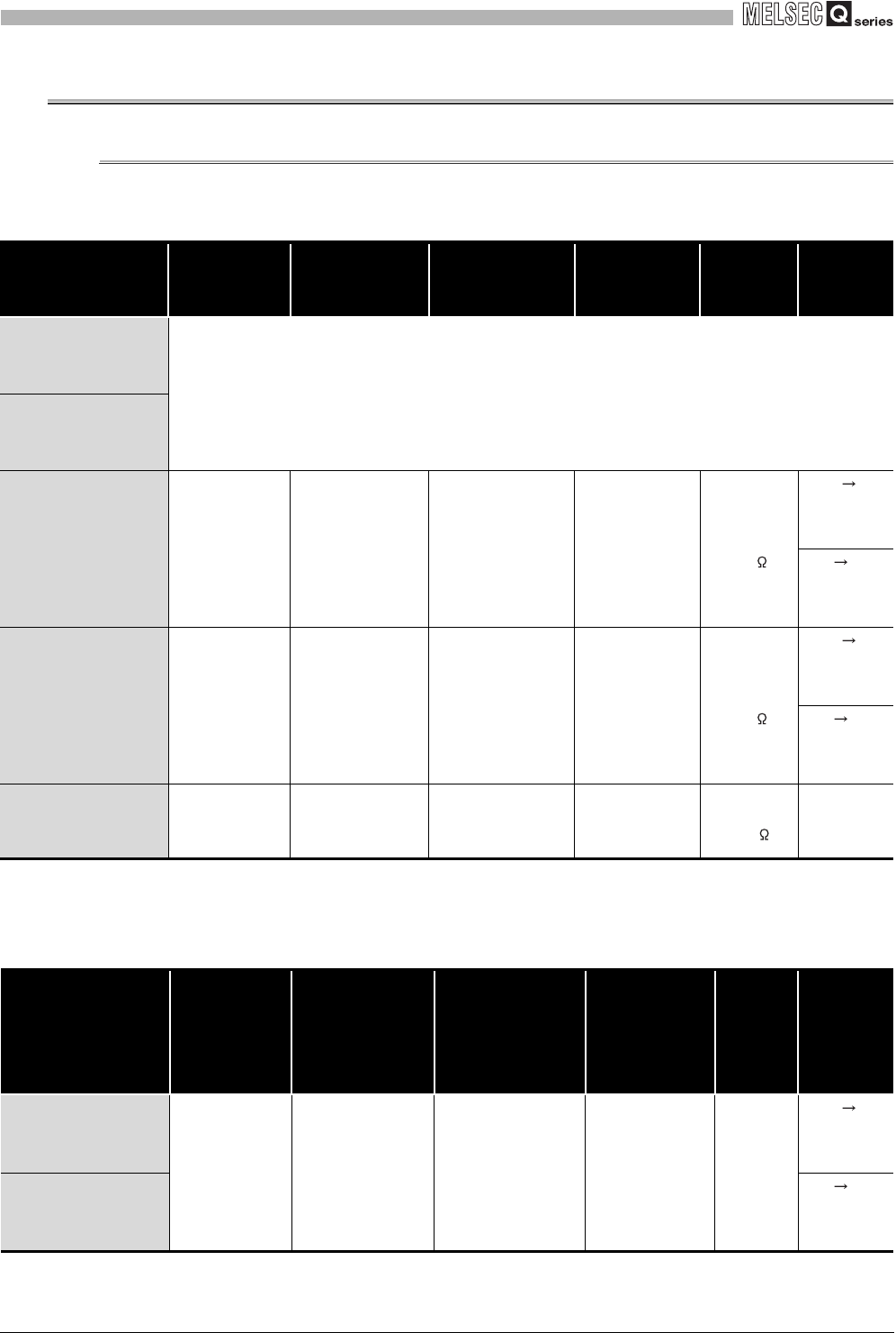
(1) Input specifications
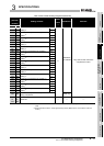
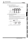
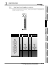
(2) Output specifications
Table 3.6 Input specifications of the QD64D2
Signal name
Rated input
voltage/
current
Operating
voltage range
ON voltage/
current
OFF voltage/
current
Input
resistance
Response
time
Phase A pulse input
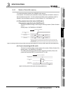
•RS-422-A compliant differential receiver
(AM26C32 (manufactured by Texas Instruments Incorporated) or equivalent)
V
IT+ differential input ON voltage (H level threshold voltage) 0.1V
VIT- differential input OFF voltage (L level threshold voltage) -0.1V
Vhys Hysteresis voltage (V
IT+ - VIT-) 60mV
(A current type line driver cannot be used.)
Phase B pulse input
Preset input
24VDC
/5mA
21.6 to 26.4VDC
21.6 to 26.4VDC
/2 to 5mA
5VDC or less
/0.1mA or less
Approx.
10k
OFF ON
0.5ms or
less
ON OFF
1.0ms or
less
Latch counter input
24VDC
/5mA
21.6 to 26.4VDC
21.6 to 26.4VDC
/2 to 5mA
5VDC or less
/0.1mA or less
Approx.
10k
OFF ON
0.5ms or
less
ON OFF
1.0ms or
less
External coincidence
output power supply
12/24V
12 or 24VDC
/8mA
(TYP 24VDC)
10.2 to 30VDC ---- ----
Approx.
3.9k
----
Table 3.7 Output specifications of the QD64D2
Signal name
Rated load
voltage
Operating load
voltage range
Maximum load
current/rush
current
Maximum
voltage drop at
ON
Leakage
current
at OFF
Response
time (rated
load,
resistance
load)
Coincidence output
No.1
12/24VDC 10.2 to 30VDC
0.5A/point
2A/common
1.5VDC
0.1mA
or less
OFF ON
0.05ms or
less
Coincidence output
No.2
ON OFF
0.1ms or
less