


4
PROCEDURES AND SETTINGS BEFORE
OPERATION
4.5 Intelligent Function Module Switch Setting
4 - 11
1
OVERVIEW
2
SYSTEM
CONFIGURATION
3
SPECIFICATIONS
4
PROCEDURES AND
SETTINGS BEFORE
OPERATION
5
FUNCTIONS
6
UTILITY PACKAGE (GX
Configurator-CT)
7
PROGRAMMING
8
TROUBLESHOOTING
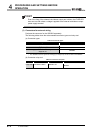
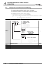
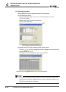
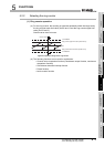
(Example) Target channel: channel 1, pulse input mode setting: 1 multiple of 2
phases, counter format: ring counter, and counter value comparison function
selection: continuous comparison function
Set the switch 1 = 1103
H.
POINT
The reserved bits in Table 4.5 are for system use, not for users.
Therefore, always fix them to 0. If used (changed from 0 to 1) by a user, the
functions of the QD64D2 are not guaranteed.
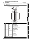
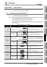
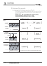
(2) Details of the intelligent function module switch setting
Table 4.6 Details of the intelligent function module switch setting
Setting item Description Reference
Pulse input mode
Set the pulse input mode for each channel.
When setting 6H to FH, a switch setting error (error code:
810) occurs.
Section 5.1.1
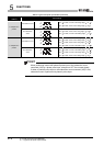
Counter format Set the counter format for each channel.
Section 5.2.1
Section 5.2.2
Counter value comparison
function selection
Set the counter value comparison function for each
channel.
Section 5.3.1
Section 5.3.2