


4
PROCEDURES AND SETTINGS BEFORE
OPERATION
4.1 Handling Precautions
4 - 1
1
OVERVIEW
2
SYSTEM
CONFIGURATION
3
SPECIFICATIONS
4
PROCEDURES AND
SETTINGS BEFORE
OPERATION
5
FUNCTIONS
6
UTILITY PACKAGE (GX
Configurator-CT)
7
PROGRAMMING
8
TROUBLESHOOTING
CHAPTER4 PROCEDURES AND SETTINGS BEFORE
OPERATION
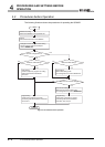
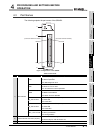
This chapter describes the operating procedures before operation, part names, settings,
and wiring of the QD64D2.
4.1 Handling Precautions
This section describes precautions on handling the QD64D2.
(1) Do not drop the module case and/or connector or apply a strong impact
to it.
(2) Do not remove the printed-circuit board of the module from the case.
Doing so will cause a failure.
(3) Be careful to prevent foreign matter such as dust or wire chips from
entering the module.
Failure to do may cause a fire, failure or malfunction.
(4) A protective film is attached to the module top to prevent foreign matter
such as wire chips from entering the module during wiring.
Do not remove the film during wiring.
Be sure to remove it for heat dissipation before system operation.
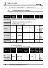
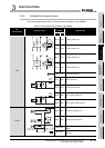
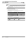
(5) Tighten the screws such as module fixing screws within the following
ranges.
* 1 The module can be easily fixed onto the base unit using the hook at the top of the module.
However, it is recommended to secure the module with the module fixing screw if the module is
subject to significant vibration.
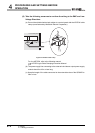
(6) When mounting the module to the base unit, insert the module fixing
projection into the fixing hole in the base unit, and mount the module
with using the hole as a supporting point.
Incorrect module mounting may cause a malfunction, failure, or drop of
the module.
Table 4.1 Tightening torque range of module fixing screw
Screw Tightening torque range
Module fixing screw (M3)
*1
0.36 to 0.48 N•m
Connector screw of module (M2.6) 0.20 to 0.29 N•m